
Method and apparatus for generating motion compensated pictures

A motion compensation and image technology, applied in the direction of image communication, interpolation processing conversion, color TV parts, etc., can solve unsatisfactory problems

Active Publication Date: 2007-11-14
INTERDIGITAL CE PATENT HLDG
View PDF0 Cites 3 Cited by
  • Summary
  • Abstract
  • Description
  • Claims
  • Application Information

AI Technical Summary

Problems solved by technology

[0004] In some cases, it is unsatisfactory to use this kind of motion estimator, especially when there is a zoom in or zoom out between two consecutive source images

Method used


Image

  • Method and apparatus for generating motion compensated pictures
  • Method and apparatus for generating motion compensated pictures
  • Method and apparatus for generating motion compensated pictures

Examples


Embodiment Construction

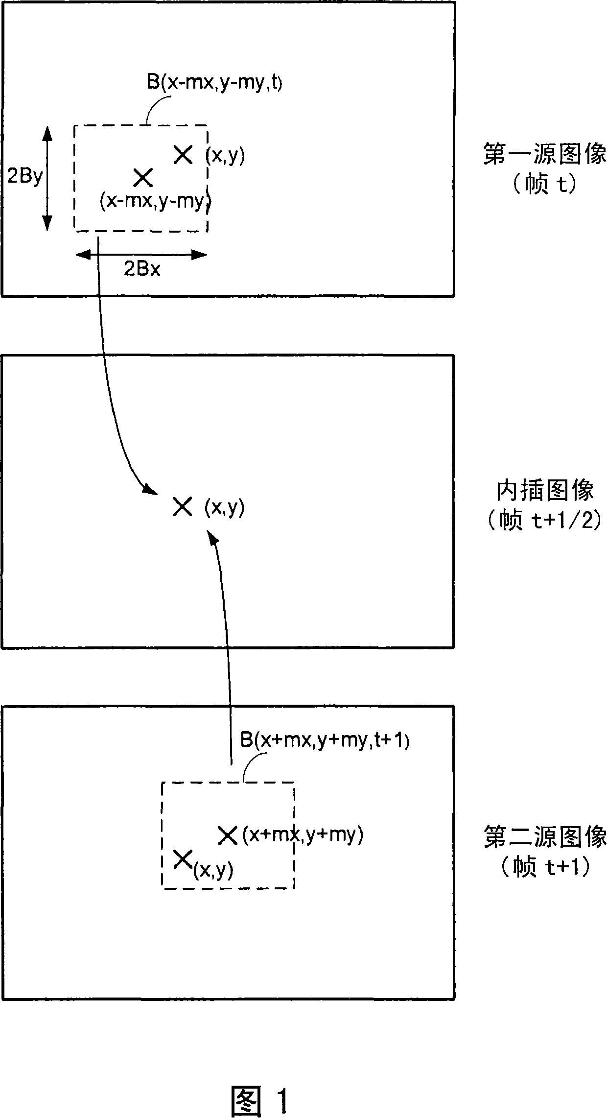
[0024] According to the invention, the method is a pixel-by-pixel calculation of the interpolated image. At the beginning of processing, there are no known pixel values ​​in this image. These values ​​are sequentially determined pixel by pixel. For example, first the pixels of the first row are respectively determined, then the pixels of the second row, and so on for the remaining pixels of the interpolated image. Other scanning methods are also possible, but regardless of the scanning method, the pixel values ​​are processed once and only once.

[0025] An interpolated image (frame t+1 / 2) is generated from a current source image (frame t), referred to as the first source image, and a subsequent source image (frame t+1), referred to as the second source image.

[0026] For each spatial direction of the image, a motion range including motion values ​​is defined. The motion value defines the motion of the interpolated image when compared to the two source images. For example...


PUM


Abstract

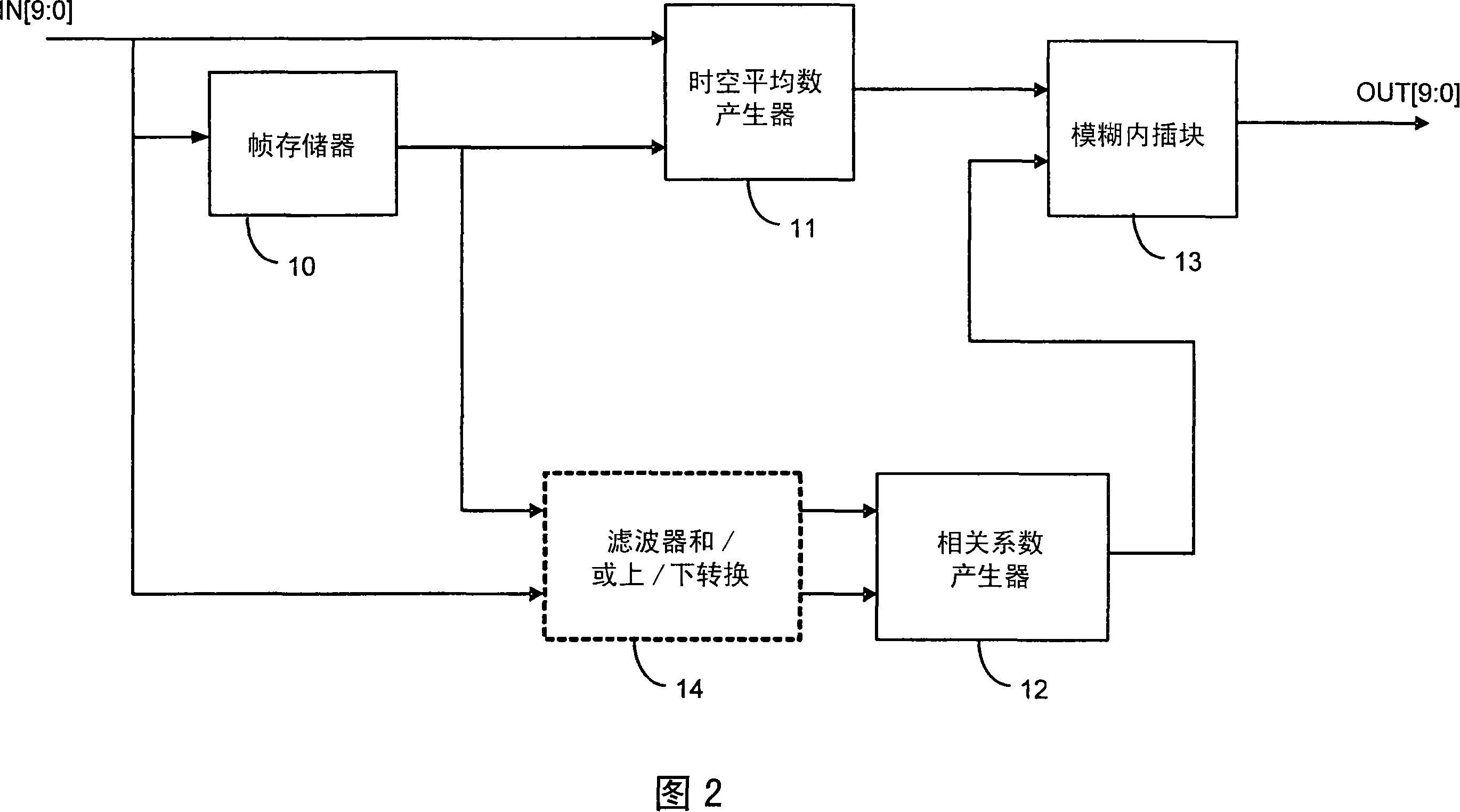
The present invention relates to a new method for generating motion com- pensated picture by interpolating two consecutive source pictures without using motion estimator. According to the invention, the interpolated picture is computed by a fuzzy method.The present invention relates to a new method for generating motion compensated picture by interpolating two consecutive source pictures without using motion estimator. For a given pixel to be interpolated, all displacements within a given search range between former and next frame are considered anf for each displacement the displaced block difference is calculated. The pixel value is then equal to the sum of each averaged pixel pair within the search range weighted by a correlation coefficient funtion of the corresponding displaced block difference.

Description

technical field [0001] The present invention relates to a new method and apparatus for interpolating motion compensated images from two consecutive source images. Background technique [0002] As we all know, in order to convert a 50Hz video signal into a 100Hz video signal, an interpolated image needs to be generated. These interpolated images should be motion compensated to avoid visual artifacts. [0003] In general, a motion vector is calculated for each pixel of the source image in the 50Hz signal using a motion estimator. A motion vector represents the pixel motion (represented by the number of pixels) between two consecutive source images. The pixel's motion vector is then used to determine the pixel's position in the interpolated image. [0004] In some cases, using such a motion estimator is unsatisfactory, especially when there is a zoom in or zoom out between two consecutive source images. Some holes appear in zoomed-in image areas, and some conflicts appear i...

Claims


Application Information

Patent Timeline
Patent Type & Authority Applications(China)
IPC IPC(8): H04N7/01H04N5/44
CPCH04N7/014H04N7/0132H04N7/0135H04N7/01H04N19/51
Inventor 塞德里克·塞柏特卡洛斯·科瑞塞巴斯腾·威特布鲁赫
Owner INTERDIGITAL CE PATENT HLDG
Learn More