Sinew-driven pseudohand finger mechanism

A tendon-driven, prosthetic hand technology, used in prostheses, medical science, artificial arms, etc., can solve the problem of unable to achieve relative movement of finger knuckles, and achieve the effects of simple structure, relative movement, and improved flexibility.

Inactive Publication Date: 2007-11-21
HARBIN INST OF TECH
View PDF0 Cites 32 Cited by
  • Summary
  • Abstract
  • Description
  • Claims
  • Application Information

AI Technical Summary

Problems solved by technology

[0004] The purpose of the present invention is to provide a tendon-driven prosthetic hand finger mechanism, which can solve the problem that the existing prosthetic hand mechanism cannot realize the relative motion of the knuckles of the fingers

Method used


Image

  • Sinew-driven pseudohand finger mechanism
  • Sinew-driven pseudohand finger mechanism
  • Sinew-driven pseudohand finger mechanism

Examples


specific Embodiment approach 1

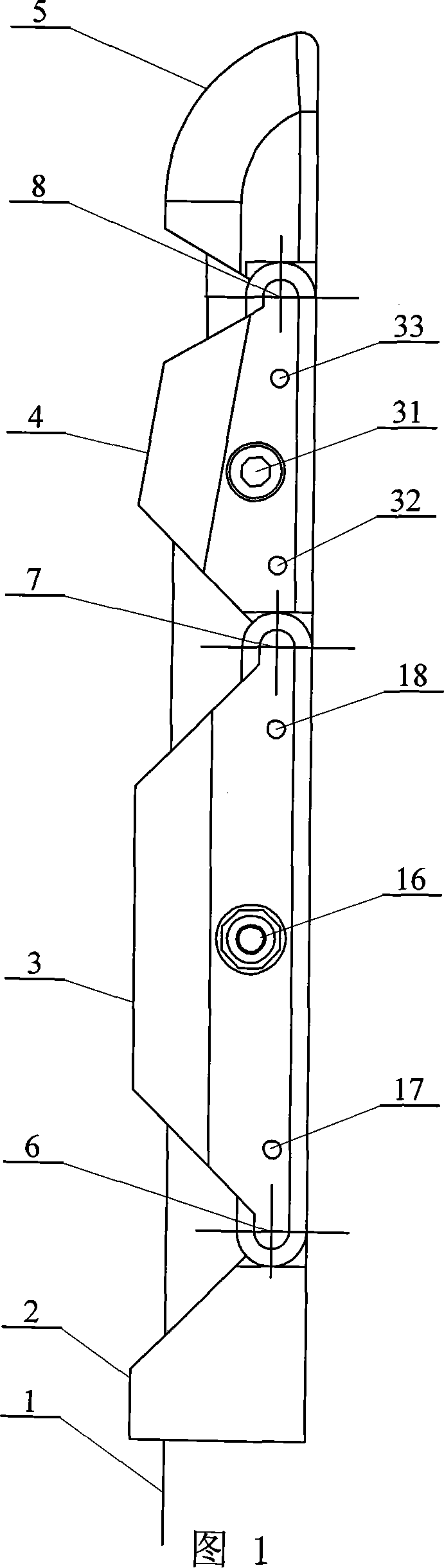
[0008] Specific Embodiment 1: This embodiment is described with reference to FIGS. 1 to 4 and 13. This embodiment consists of a base 2, a base phalanx 3, an intermediate phalanx 4, an end phalanx 5, a driving tendon 1, a base joint 6, It consists of an intermediate joint 7 and an end joint 8; the base knuckle 3 is connected to the base 2 through the base joint 6, the base knuckle 3 is connected to the middle knuckle 4 through the intermediate joint 7, and the middle knuckle 4 is connected to the end The knuckles 5 are connected through the rotation of the terminal joint 8, and one end of the driving tendon 1 passes through the base 2, the base phalanx 3, the middle phalanx 4, and the terminal phalanx 5 respectively from bottom to top, and is fixedly connected to the terminal phalanx 5 , and the driving tendon 1 is located on the outside of the base joint 6, intermediate joint 7 and terminal joint 8, and the length of each phalanx is determined according to the length of each fi...

specific Embodiment approach 2

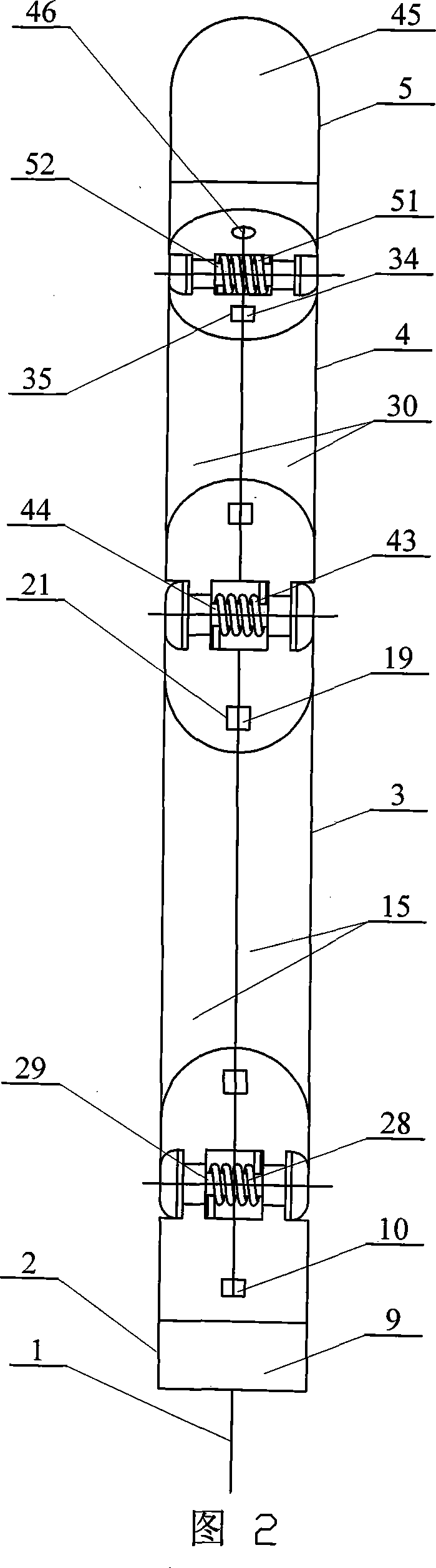
[0009] Specific embodiment two: This embodiment is described in conjunction with Fig. 2, Fig. 5 and Fig. 6. The base 2 of this embodiment is composed of a base body 9 and a base spring tube 10; the two connecting ears 11 of the base body 9 are The base joint shaft holes 12 are respectively provided, and the seat body 9 is provided with an axial through hole 13, and the base spring tube 10 is embedded in the axial through hole 13, and the outer parts of the two connecting ears 11 of the seat body 9 Base limit shoulders 14 are respectively provided on the end faces, and the driving tendon 1 passes through the base spring tube 10 . With such arrangement, the structure is simple, and the use is safe and reliable. In addition, the use of the base spring tube can reduce the movement friction between the driving tendon and the base. Other components and connections are the same as those in the first embodiment.

specific Embodiment approach 3

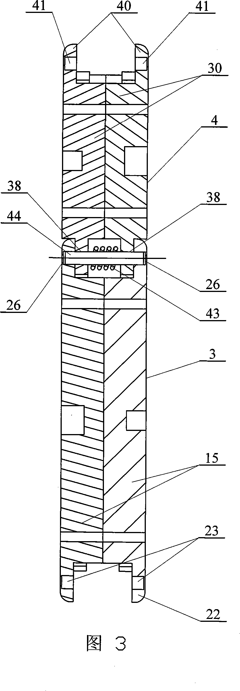
[0010] Specific embodiment three: This embodiment is described in conjunction with Fig. 1, Fig. 2, Fig. 7 and Fig. 8, the base knuckle 3 of this embodiment is composed of two half-base knuckles 15, a base knuckle screw 16, a first base knuckle The positioning pin 17, the second base knuckle positioning pin 18, and the base knuckle spring tube 19 are composed; the two half-base knuckles 15 are symmetrically placed left and right, and the two half-base knuckles 15 pass through the base knuckle screw rod 16, the first knuckle The base knuckle positioning pin 17 and the second base knuckle positioning pin 18 are connected, and the corresponding positions on the corresponding side end faces of the two half-base knuckles 15 are respectively provided with inner through grooves 20, and the two inner through grooves 20 are formed. The through groove 20 is combined into an inner hole 21, the base knuckle spring tube 19 is embedded in the inner hole 21, and the corresponding side end surf...


PUM


Abstract

The invention is concerned with a false finger framework driven by muscle, involving a kind of false finger framework. The existing false hand framework cannot solve the opposite movement of finger knuckle. The base knuckle and base seat connect in moving through base joint, the base knuckle and middle knuckle connect in moving with middle joint, and the middle knuckle and end knuckle connect in moving with end joint. The one end of driven muscle connects with end knuckle through base seat, base knuckle, middle knuckle and end knuckle, and it is at the outside of base joint, middle joint and end joint. This invention enhances the agility of finger without adding the freedom of finger to false hand with easy structure and credible safety. It realizes the opposite movement of finger knuckle and the finger can fit for catching objects with different shapes and sizes.

Description

technical field [0001] The invention relates to a prosthetic finger mechanism. Background technique [0002] The human hand is the most complex and delicate tool for human beings to survive and work. The absence of hands not only makes people lose their important functions but also suffers psychological damage. Due to reasons such as traffic accidents, work-related injuries and diseases, the number of people with disabilities has increased significantly, which is a serious social problem worldwide. [0003] An ideal prosthetic hand should be the same in shape and function as a real hand. It can not only replace the sensory and motor functions of a human hand, but also have a beautiful appearance like a human hand. But current technology is far from meeting this ideal requirement. The human body upper limb mechanism model has 27 degrees of freedom, of which the finger part has 20 degrees of freedom, but the current scientific level cannot achieve an electronic prosthetic ha...

Claims


Application Information

Patent Timeline
Patent Type & Authority Applications(China)
IPC IPC(8): A61F2/54A61F2/68
Inventor 刘伊威刘宏
Owner HARBIN INST OF TECH
Why Eureka
Try Eureka