Three-dimension measuring method and device
A technology of three-dimensional measurement and measurement data, which can be used in measurement devices, optical devices, instruments, etc., and can solve problems such as gaps
- Summary
- Abstract
- Description
- Claims
- Application Information
AI Technical Summary
Problems solved by technology
Method used
Image

Examples
Embodiment 2
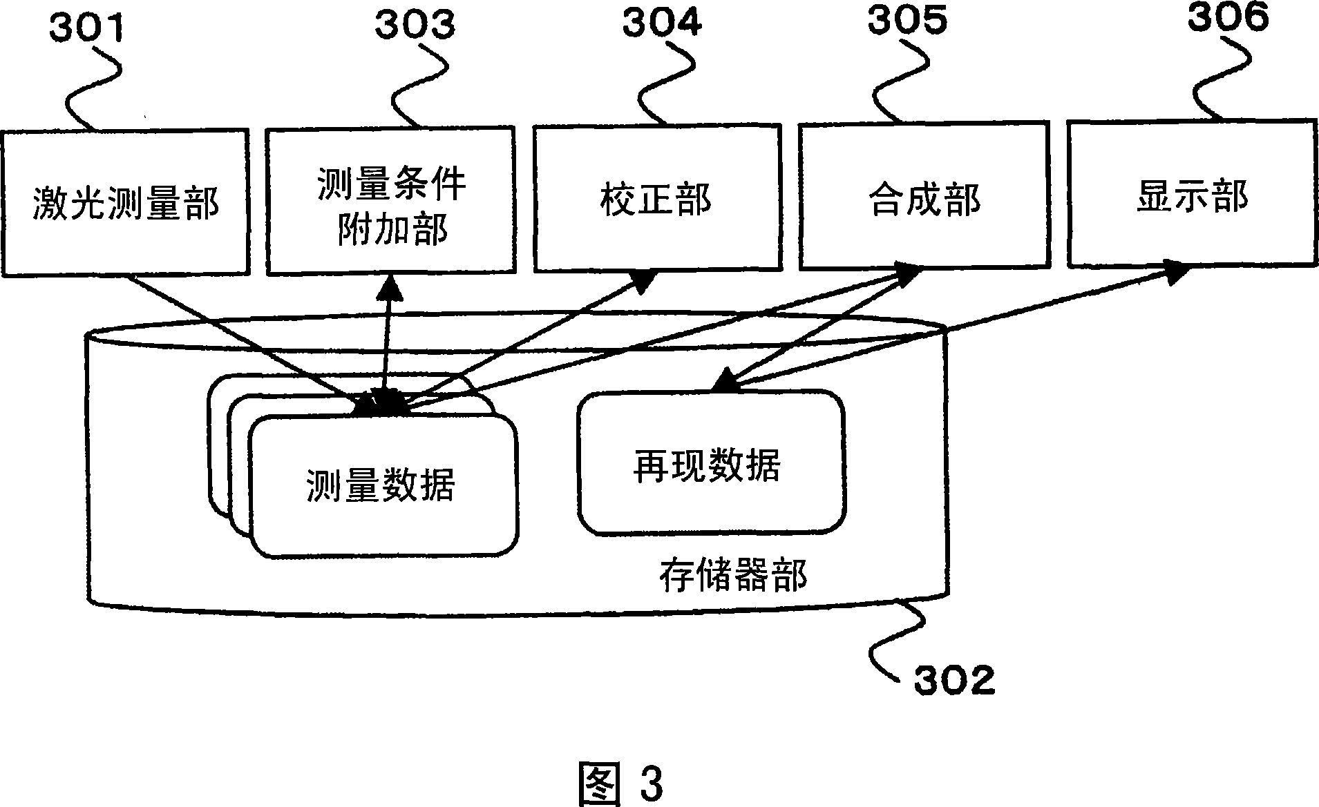
[0051] Fig. 14 shows a second embodiment of the present invention. The laser measurement unit 301 performs laser measurement of an object. Data after laser measurement is stored in the memory unit 302 . The measurement condition adding unit 303 adds measurement condition data to the laser measurement data stored in the memory unit 302 . The synthesizing unit 305 combines and synthesizes the positions of measurement data measured from a plurality of directions stored in the memory unit 302 to generate reproduced data. The generated playback data is stored in the memory unit 302 . The level difference (level difference) evaluation unit 1401 evaluates whether or not there is a level difference in the reproduced data stored in the memory unit 302 . When the level difference evaluation unit 1401 evaluates that there is a level difference, the correction unit 304 corrects the measurement data stored in the memory 302 .
[0052] In detail, the level difference evaluation unit 140...
Embodiment 3
[0054] Fig. 16 shows a third embodiment of the present invention. In the laser measurement step 1601, laser measurement of an object is performed from multiple directions to generate measurement data. In the measurement condition addition step 1602, measurement conditions are added to the measurement data generated in the laser measurement step 1601 described above. In the correction step 1603 , the measurement data generated in the laser measurement step 1601 is corrected according to the measurement conditions added in the measurement condition addition step 1602 . Synthesizing step 1604, combining the positions of the measurement data corrected in the above-mentioned correcting step 1603, and then synthesizing them to generate reproduction data. In the display step 1605, the reproduced data generated in the synthesis step 1604 is displayed.
[0055] The measurement condition addition step 1602 has, for example, a configuration as shown in FIG. 17 in detail. In the measur...
Embodiment 4
[0059] Fig. 20 shows a fourth embodiment of the present invention. In the laser measurement step 1601, laser measurement is performed on an object from a plurality of directions to generate measurement data. The measurement condition addition step 1602 is to add measurement conditions to the measurement data generated in the above-mentioned laser measurement step 1601 . In the synthesizing step 1604, the measurement data generated in the laser measurement step 1601 are positionally synthesized and merged to generate reproduction data. In the level difference evaluation step 2001, it is evaluated whether or not there is a level difference in the reproduced data generated in the above-mentioned synthesizing step 1604. When it is evaluated in step 2001 of level difference evaluation that there is a level difference, in step 1603 of correction, the measurement data generated in step 1601 of laser measurement described above is corrected. Combining data 1604, the measurement data...
PUM
 Abstract
Description
Claims
Application Information
 - R&D Engineer
- R&D Manager
- IP Professional
- Industry Leading Data Capabilities
- Powerful AI technology
- Patent DNA Extraction
Browse by: Latest US Patents, China's latest patents, Technical Efficacy Thesaurus, Application Domain, Technology Topic.
© 2024 PatSnap. All rights reserved.Legal|Privacy policy|Modern Slavery Act Transparency Statement|Sitemap