Method for scanning entry safety landing area in moon detector suspension stage
A safe landing and detector technology, which is applied in the direction of instruments, measuring devices, surveying and navigation, etc., can solve the problem of not seeing the selection method of the landing area, and achieve the effect of ensuring the safety of landing
- Summary
- Abstract
- Description
- Claims
- Application Information
AI Technical Summary
Problems solved by technology
Method used
Image
Examples
Embodiment 1
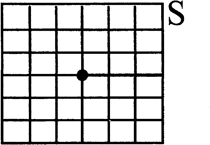
[0022] The plane resolution of the lunar surface imaging sensor is 0.1m, and the height information of every point on the lunar surface at an interval of 0.1m can be obtained through the lunar surface imaging sensor. Such as figure 1 As shown, the area occupied by the lunar probe in the case of landing is defined as the unit area S, and the center of the unit area S is defined as the landing center. The width of each grid in the figure is 0.1m. If the unit area S is 0.2m×0.2m, then S has height data of 3×3 points in total.
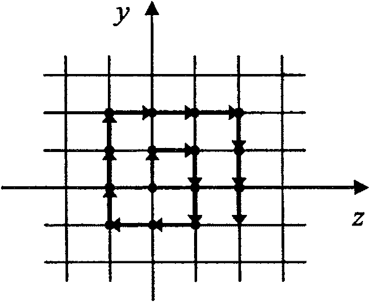
[0023] The point on the lunar surface corresponding to the current lunar probe is the initial judgment point of the landing center, and the landing center is moved point by point from the inside to the outside in a clockwise spiral form, such as figure 2 As shown in , all the height data in the unit area S where each landing center is located are calculated to determine whether the landing area of the corresponding unit area is safe.
[0024] The cond...
Embodiment 2
[0070] The plane resolution of the lunar surface imaging sensor is 0.1m, and the height information of every point on the lunar surface at an interval of 0.1m can be obtained through the lunar surface imaging sensor. Such as figure 1 As shown, the area occupied by the lunar probe in the case of landing is defined as the unit area S, and the center of the unit area S is defined as the landing center. The width of each grid in the figure is 0.1m. If the unit area S is 0.2m×0.2m, then S has height data of 3×3 points in total.
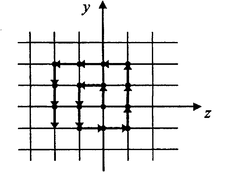
[0071] The point on the lunar surface corresponding to the current lunar probe is the initial judgment point of the landing center, and the landing center is moved point by point from the inside to the outside in a counterclockwise spiral form, such as image 3 As shown in , all the height data in the unit area S where each landing center is located are calculated to determine whether the landing area of the corresponding unit area is safe.
[0072] Th...
Embodiment 3
[0107] The plane resolution of the lunar surface imaging sensor is 0.1m, and the height information of every point on the lunar surface at an interval of 0.1m can be obtained through the lunar surface imaging sensor. Such as figure 1 As shown, the area occupied by the lunar probe in the case of landing is defined as the unit area S, and the center of the unit area S is defined as the landing center. The width of each grid in the figure is 0.1m. If the unit area S is 0.2m×0.2m, then S has height data of 3×3 points in total.
[0108] The point on the lunar surface corresponding to the current lunar probe is the initial judgment point of the landing center, and the landing center is moved from the inside to the outside in a circular manner, such as Figure 4 As shown in , all the height data in the unit area S where each landing center is located are calculated to determine whether the landing area of the corresponding unit area is safe.
[0109] The conditions for a safe lan...
PUM
 Abstract
Description
Claims
Application Information
 - R&D
- Intellectual Property
- Life Sciences
- Materials
- Tech Scout
- Unparalleled Data Quality
- Higher Quality Content
- 60% Fewer Hallucinations
Browse by: Latest US Patents, China's latest patents, Technical Efficacy Thesaurus, Application Domain, Technology Topic, Popular Technical Reports.
© 2025 PatSnap. All rights reserved.Legal|Privacy policy|Modern Slavery Act Transparency Statement|Sitemap|About US| Contact US: help@patsnap.com


