Method and device for lightning arresting switch

A lightning protection device and switch technology, applied in circuit devices, protection against overvoltage, static electricity, etc., can solve the problems of equipment that cannot be suppressed and eliminated, and achieve the effect of a wide range of equipment and a high success rate

Inactive Publication Date: 2007-11-21
庄洪春
View PDF1 Cites 5 Cited by
  • Summary
  • Abstract
  • Description
  • Claims
  • Application Information

AI Technical Summary

Problems solved by technology

The third is the overvoltage generated by nearby or distant lightning strikes on the line, which is transmitted to the microelectronic equipment through the line to cause lightning damage.
The above-mentioned intelligent lightning protection ball technology has sufficie

Method used


Image

  • Method and device for lightning arresting switch
  • Method and device for lightning arresting switch

Examples


Embodiment Construction

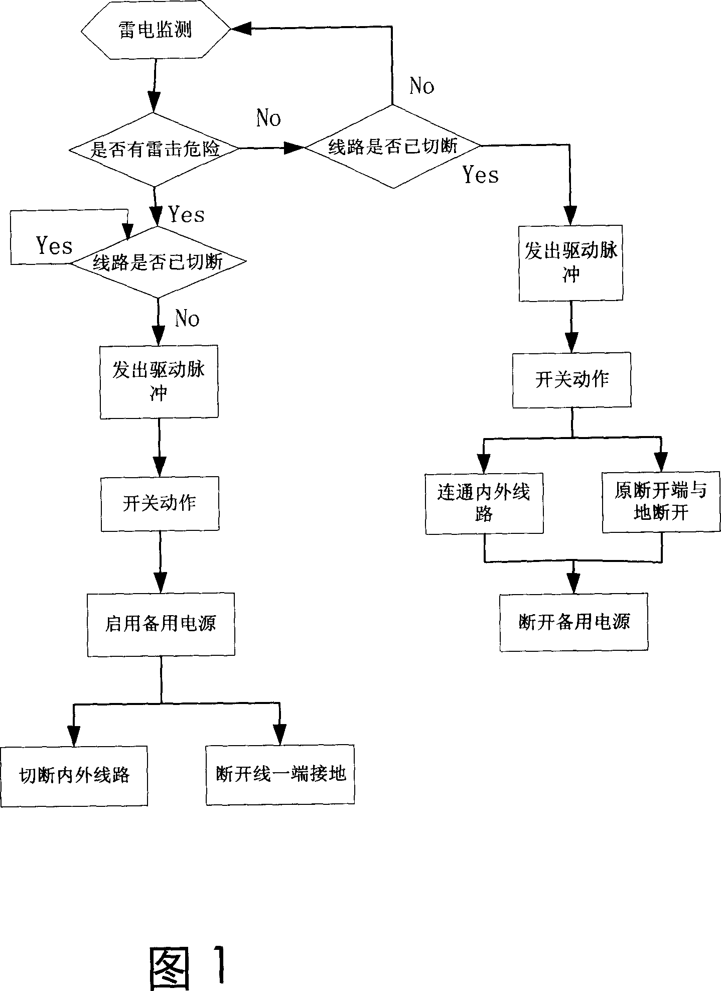
[0034] As shown in Figure 1, it is a flow chart of a preferred embodiment applied to the protection of microelectronic equipment; it adopts an automatic real-time monitoring method to ensure the safety of microelectronic equipment.

[0035] First, the lightning is monitored by the lightning monitoring device, that is, the danger of lightning strike is judged. When the lightning monitoring signal exceeds a threshold, it is judged whether the indoor and outdoor lines are cut off. Send a signal to the control circuit, and the control circuit sends a driving pulse to start the automatic switch device, connect the running equipment and the backup power supply, and use it to supply power to it, and then disconnect the internal equipment of the protected building from all external equipment. The connection of the line, connect one end of the cut line with the lightning protection ball;

[0036] On the other hand, if the lightning monitoring device does not detect the danger of lightn...


PUM


Abstract

This is a lighting device and the method. A monitoring signal of lighting is compared with a threshold, in case of larger, break the linkage between the inner and outer line. The device includes a lightning monitor, control circuit and automatic shut off element.

Description

technical field [0001] The invention relates to a lightning protection method and device, in particular to a method and device for avoiding lightning damage caused by line intrusion. Background technique [0002] Lightning protection technology has a research history of nearly 3 centuries. The classic lightning rod was invented by Franklin in the 1750s. The principle is to use a grounding conductor needle that is higher than the protected building. When there is a danger of lightning strike, the electric field intensity of the needle tip first reaches the value of breaking down the air and is struck by lightning first, thus protecting the building. [0003] In today's modernized and informationized society, more and more microelectronic devices indoors cannot withstand the electromagnetic radiation generated by lightning rods leading to the ground and are damaged. Lightning rods cannot protect modern information equipment. The progress of the times requires the adaptation a...

Claims


Application Information

Patent Timeline
IPC IPC(8): H02H3/20H02J9/06H05F3/02
CPCY02B70/30Y04S20/20
Inventor 庄洪春
Owner 庄洪春
Why Eureka
Try Eureka