
Synchronous generator for integrated rotary-magnetic external rotor oil press

A technology of synchronous generator and external rotor, which is applied to synchronous motors with stationary armatures and rotating magnets, etc., which can solve the problems of large energy waste, large volume, and low efficiency, and achieve improved efficiency, small volume, and high efficiency Effect

Inactive Publication Date: 2007-11-21
何根洪
View PDF0 Cites 1 Cited by
  • Summary
  • Abstract
  • Description
  • Claims
  • Application Information

AI Technical Summary

Problems solved by technology

[0003] The present invention aims to provide an integrated magnet-rotating outer rotor oil-engine synchronous generator, so as to overcome the defects of the prior art such as large volume, heavy weight, low efficiency, and large energy waste, and achieve improved efficiency, reduced weight, and convenient operation. purpose of work life

Method used


Image

  • Synchronous generator for integrated rotary-magnetic external rotor oil press
  • Synchronous generator for integrated rotary-magnetic external rotor oil press
  • Synchronous generator for integrated rotary-magnetic external rotor oil press

Examples


Embodiment Construction

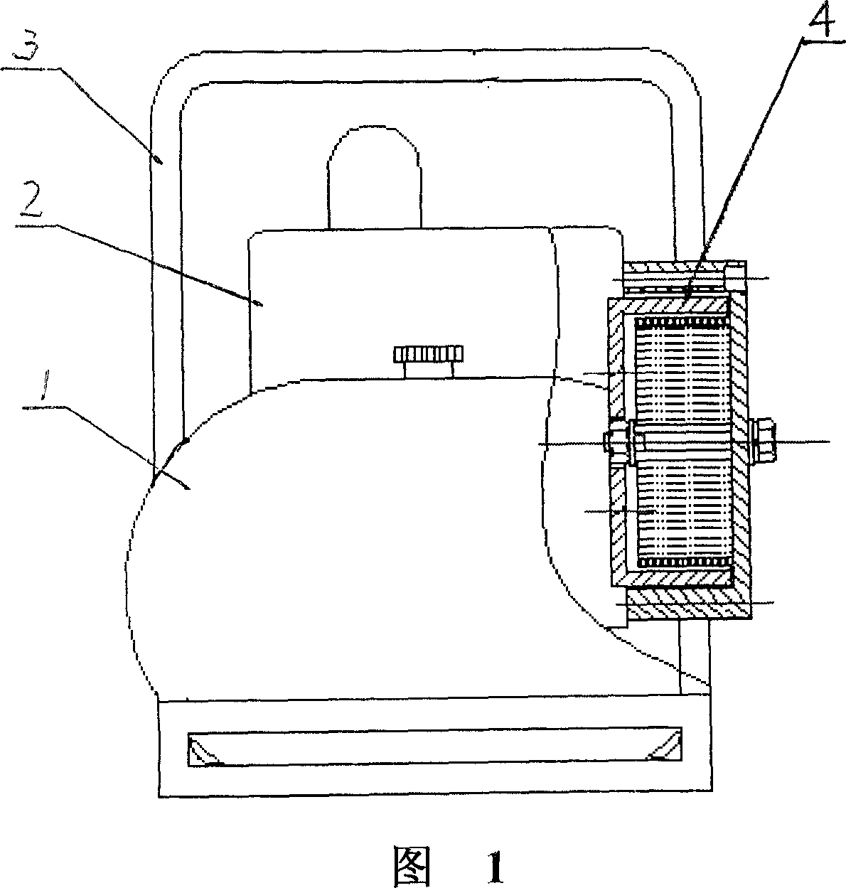
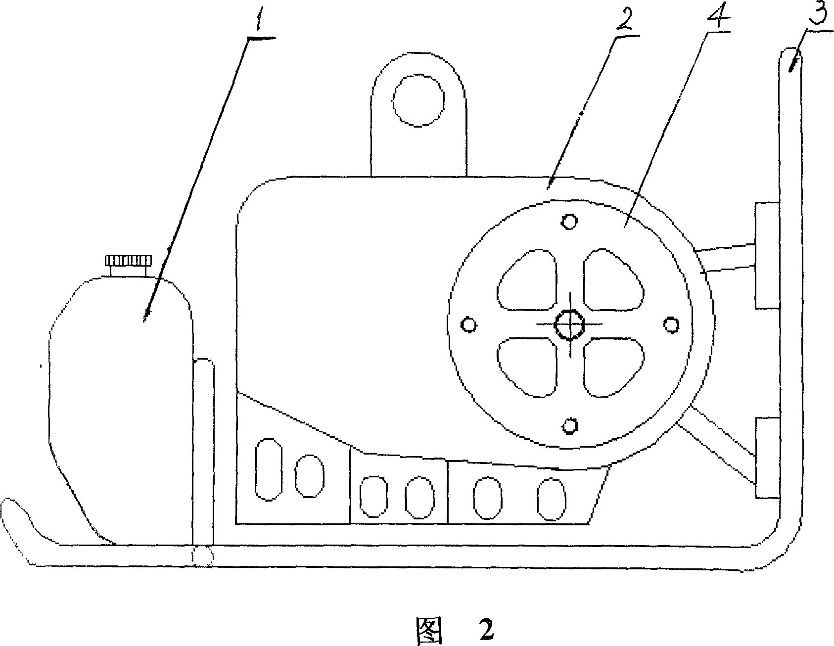
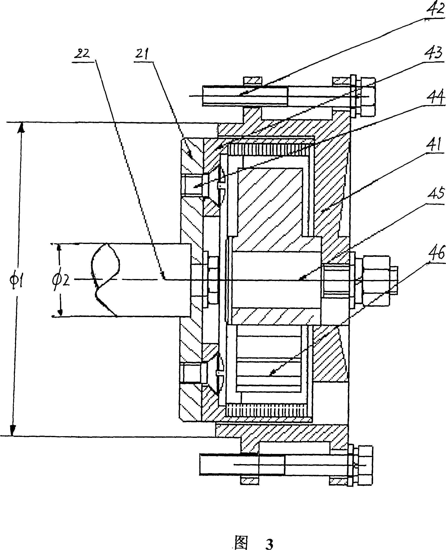
[0014] Referring to the accompanying drawings, the integrated rotating magnet outer rotor synchronous generator of the present invention is composed of a fuel tank 1, an oil generator 2, a support 3 and a rotating magnetic outer rotor synchronous generator 4, and the fuel tank 1 and the gasoline engine Or the oil machine 2 composed of a diesel engine is installed on the support 3, the magnetic outer rotor 43 of the generator 4 is fixed on the rotating shaft of the oil machine, and the stator 46 of the generator is concentrically arranged in the magnetic outer rotor 43 and passed through the motor. The stator fixing sleeve 41 is fixedly connected with the housing of the oil machine, and there is an appropriate gap between the stator 46 and the magnetic outer rotor 43, so that the generator 4 is generally fixed on the rotating shaft and the housing of the oil machine 2 like a small part, reducing the Reduced volume and weight (the oil engine generator looks like a single oil engi...


PUM


Abstract

The invention has an oil engine composed of a gasoline engine or a diesel engine. It features a magnetic outer rotor made out of the flywheel of the oil engine; in the magnetic outer rotor, a stator with winding coil is mounted; after the magnetic outer rotor turns, the winding of inner stator is induced to produce electric potential which is outputted via the leading-out wire.

Description

Technical field [0001] The content of the present invention belongs to the technical field of electromechanical devices, and relates to an improved structure of an oil engine (gasoline engine or diesel engine) generator. Background technique [0002] With the rapid development of today's social economy, the contradiction of energy shortage in the world has become increasingly obvious, and power cuts and blackouts often occur in daily life and production. Due to the needs of emergency production, life or field work, oil-driven generators have been widely used. A conventional diesel engine generator is mainly composed of three parts, namely, the oil engine, the generator, and the coupling or connecting belt. The oil engine and the generator have their own independent fixing brackets and foundation parts, and the actual structure of the product has a volume Large size, heavy weight, low efficiency, high fuel consumption, difficult relocation and other defects, it is not suitab...

Claims


Application Information

Patent Timeline
Patent Type & Authority Applications(China)
IPC IPC(8): H02K21/22
Inventor 何根洪韩彬霞呼刚云赵安民
Owner 何根洪
Learn More