Dew-point humididier and temperature control for corresponding gas

A technology of humidifier and wet gas, which is applied in the direction of humidity control, control/regulation system, non-electric variable control, etc. It can solve the problems of difficult precise control of humidity and achieve the effect of accurate temperature measurement and thermal efficiency improvement

Inactive Publication Date: 2007-11-21
张超迥
View PDF5 Cites 13 Cited by
  • Summary
  • Abstract
  • Description
  • Claims
  • Application Information

AI Technical Summary

Problems solved by technology

This phenomenon makes precise control of humidity difficult because the gas and vapor are not uniformly mixed

Method used


Image

  • Dew-point humididier and temperature control for corresponding gas
  • Dew-point humididier and temperature control for corresponding gas
  • Dew-point humididier and temperature control for corresponding gas

Examples


Embodiment Construction

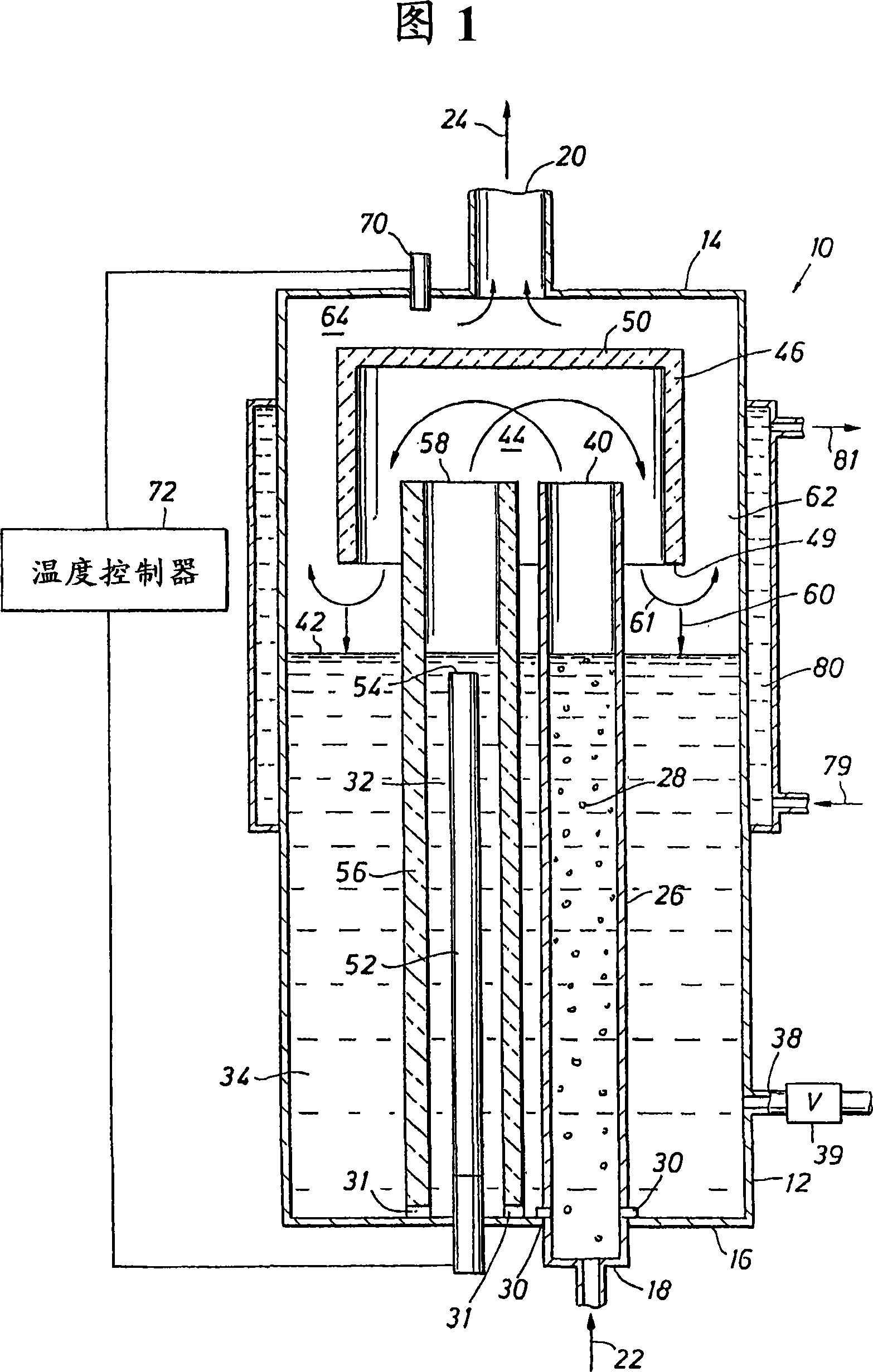
[0031] Figure 1 shows the core structure of a humidifier 10 of the present invention and the method of humidifying gas. Humidifier 10 basically includes a container 12 having a top 14 and a bottom 16, which is preferably cylindrical. Inlet line 18 introduces drying gas into vessel 12 and outlet 20 directs humidified gas from the vessel. The entry of drying gas into the container is shown by arrow 22 and the exit of humidified gas from the container is shown by arrow 24 .

[0032] The drying gas 22 having a temperature below the set dew point temperature begins to be humidified by passing through the pre-humidifier 26 . The dry gas 22 is bubbled through the pre-humidifier 26 to form water bubbles 28, which rise through the pre-humidifier, picking up some moisture and being heated to a higher temperature by the water in the pre-humidifier column. The pre-humidifier 26 is formed as an elongated container such as a tube with an opening 30 preferably along the bottom of the tube ...


PUM


Abstract

A method of humidifying gases to 100% relative humidity and a humidifier to carry out such a method are provided to humidify gases for fuel cells and for other applications. The humidification of gases is thermally controlled and thermal energy is managed to provide an efficient system. A pre-humidifier accommodates a wide range of flow rates of dry gas to initially humidify and pre-heat the gas, and a boiler provides steam to mix with the effluent from the pre-humidifier to humidify the gas to saturation. A thermal insulator between the boiler and bulk water and / or prehumidifier enhances the steam generation from the boiler and prevents direct heating of water or gases by heat from the boiler. Above the boiler, bulk water, and prehumidifier, a mixing chamber further functions as a condenser and water separator. The mixing chamber provides a space for mixing gases and steam and separates saturated gases from condensed water. By vapor condensation during the mixing, the gas can be humidified completely to its dew point at given temperature and pressure conditions.

Description

field of invention [0001] This invention relates generally to the field of continuous gas flow humidification systems and, more particularly, to methods and systems for humidifying gaseous reactants or other gases used in fuel cells. The invention also relates to the field of temperature control and tracking of humidified gases. Background technique [0002] The humidifier described in U.S. Patent No. 6,338,472 to Shimazu et al., like others in the field of the invention, is commonly used to humidify process gases that may be supplied to a solid-phase polymer fuel cell (SPFC ) anode or cathode. The process gas includes fuel gas supplied to the anode and oxidizing gas supplied to the cathode. The solid-phase polymer fuel cell generates electricity by an electrochemical reaction in which protons generated by gas supplied to the anode are transferred to the cathode through an electrolyte membrane and react with oxidizing gas supplied to the cathode to generate water. However...

Claims


Application Information

Patent Timeline
Patent Type & Authority Applications(China)
IPC IPC(8): H01M8/04B01F3/04F24F3/04G05D22/00B01D1/00B01D1/14B01D3/34F24F6/00G05D22/02B01D47/00B01F5/06H01M8/10
CPCB01F5/0603H01M8/04126H01M2008/1095H01M8/04164Y10S261/10Y02E60/50H01M8/04291B01F25/421
Inventor 张超迥
Owner 张超迥
Why Eureka
Try Eureka