Tensioning device for spinning machine lower leather collar

A tensioning device and spinning machine technology, applied in spinning machines, textiles, papermaking, drafting equipment, etc., to achieve the effects of reducing wrap angle, reducing probability, and reducing friction

Inactive Publication Date: 2007-11-28
山西鸿基实业有限公司
View PDF0 Cites 4 Cited by
  • Summary
  • Abstract
  • Description
  • Claims
  • Application Information

AI Technical Summary

Problems solved by technology

[0003] The technical problem to be solved by the present invention is to provide a tensioning device for the lower apron of the spinning machine, so as to avoid excessive wrapping angle of the lower apron on the lower pin, so as to reduce yarn formation caused by slipping of the lower apron and being squeezed. Poor quality and damaged parts

Method used


Image

  • Tensioning device for spinning machine lower leather collar
  • Tensioning device for spinning machine lower leather collar
  • Tensioning device for spinning machine lower leather collar

Examples


Embodiment Construction

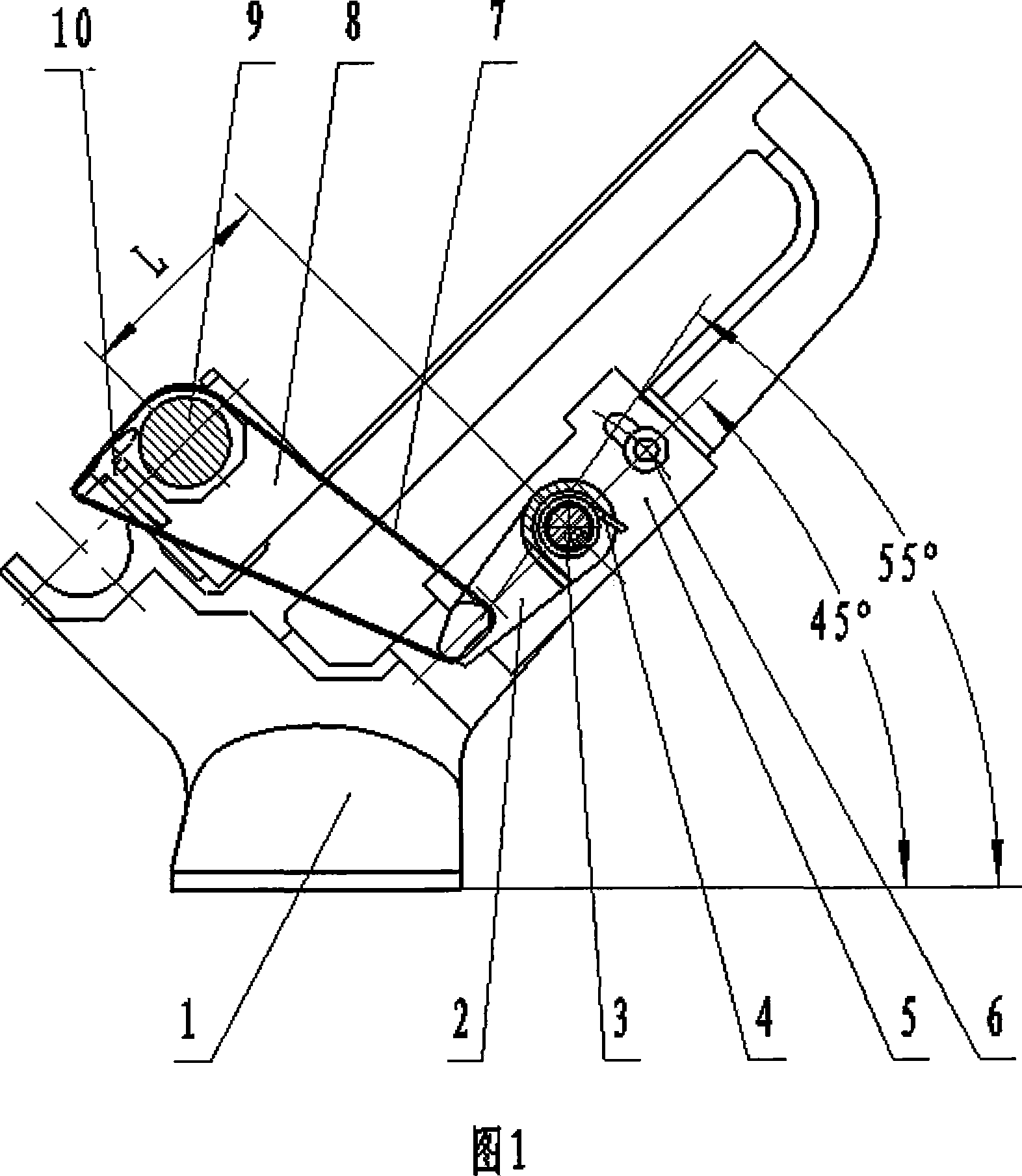
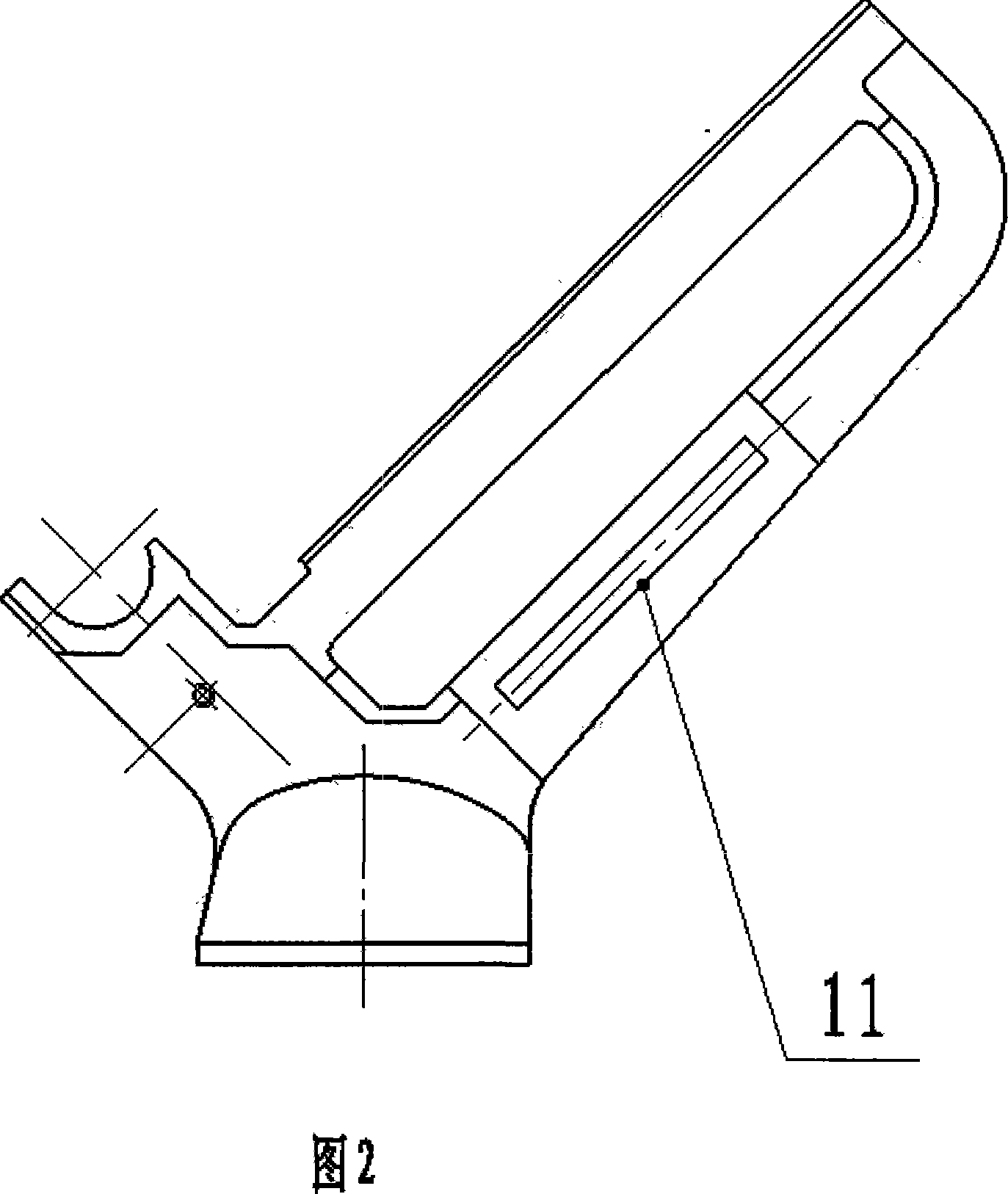
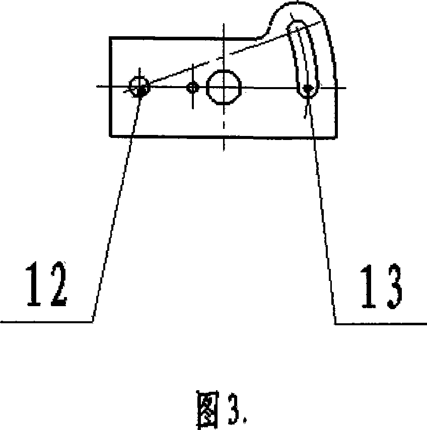
[0009] As shown in Figure 1: the apron tensioning device includes roller seat 1, tension frame 2, tension frame support rod 3, torsion spring 4, tension rod mounting plate 5, screw 6, lower apron 7, middle roller slide seat 8. The middle roller 9, the lower pin 10, the middle roller 9 and the lower pin 10 are arranged on the middle roller slide 8, the middle roller slide 8 is arranged on the roller seat 1, the tension frame 2 connects the tension frame support rod through the torsion spring 4 3 connection, a long hole 11 is arranged on the reinforcing rib of the roller seat 1, a tension rod mounting plate 5 is arranged on the long hole 11, and two screw holes are arranged on the tension rod mounting plate 5, one is a round hole 12, and the other is a round hole 12. It is a long hole 13, and the tension rod mounting plate 5 is arranged on the roller seat 1 through the screw 6. The angle of the tension rod mounting plate 5 on the roller seat 1 is 45 degrees. The frame 2 and the ...


PUM


Abstract

The invention relates to a tensioner of the spinning machine lower leather collar. The middle roller and the lower pin are set on the middle roller sliding seat which is set on the roller seat. The tension frame is connected with the supporting rod by the reed. A long hole is set on the reinforced rib in roller seat, which is set with the tension rod installing plate which is set on the roller seat through the bolt. The installing plate is set with the tension frame, the middle roller through the tension frame supporting rod which is connected with the lower pin through the lower leather collar. The tension frame can be adjusted in the 45: angle line to decrease the probability of the lower leather collar crushed between the lower pin and middle roller.

Description

1. Technical field: [0001] The invention belongs to a spinning machine, in particular to a tensioning device for the lower apron of the spinning machine. 2. Background technology: [0002] On the current spinning machine, most of the middle rollers of the drafting part adopt long and short apron devices, and the lower apron is a long apron, which needs to be tensioned. The method that tensioning adopts is to install a cross bar between two roller seats, use the torsion spring and the tension frame that pass on the cross bar to tension the lower apron. But the position of the cross bar is fixed, so when the spinning process is changed, the wrap angle of the lower apron on the lower pin and the middle roller will change when the middle roller moves, and when the middle roller moves forward, the lower apron is on the lower pin The wrap angle of the lower apron will increase, so that the friction force of the lower apron on the lower pin will increase, and at the same time, the...

Claims


Application Information

Patent Timeline
Patent Type & Authority Applications(China)
IPC IPC(8): D01H5/86
Inventor 裘永清刘钢杨卫萍董俊明唐海庆高志毅高小改
Owner 山西鸿基实业有限公司
Why Eureka
Try Eureka