A drive structure of an elevator

A driving structure and elevator technology, which is applied to elevators, elevators, transportation and packaging in buildings, etc., can solve the problems of occupying the top space of elevators, large size of fixed pulley 1, and short life of steel wire ropes, reducing volume and configuration. The effect of the amount of heavy objects and the small wrap angle of the traction sheave

Active Publication Date: 2016-04-20
江门市蒙德电气股份有限公司
View PDF12 Cites 0 Cited by
  • Summary
  • Abstract
  • Description
  • Claims
  • Application Information

AI Technical Summary

Problems solved by technology

[0003] The driving connection structure adopted by traditional elevators has the following disadvantages: one is the installation problem of the fixed pulley 1 and the driving motor. The fixed pulley 1 and the driving motor must be arranged on the top of the elevator shaft, usually at the top of the floor. 1 and the drive motor, if there is no elevator room on the floor, it is necessary to reserve a space inside the elevator shaft to install the fixed pulley 1 and the drive motor. Since the diameter of the fixed pulley 1 is more than 40 times the diameter of the steel cable according to national regulations, generally It is set between 45 and 55 times the diameter of the wire rope, resulting in a large volume of the fixed pulley 1, which takes up a lot of space on the top of the elevator, and has the disadvantages of a large amount of wire rope and a short service life caused by reverse bending of the wire rope; the second is the counterweight box 4 The weight 5 inside needs to be set with a larger quality, and the cost is higher

Method used


Image

  • A drive structure of an elevator
  • A drive structure of an elevator

Examples


Embodiment Construction

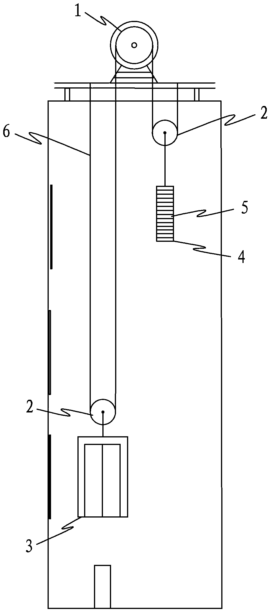
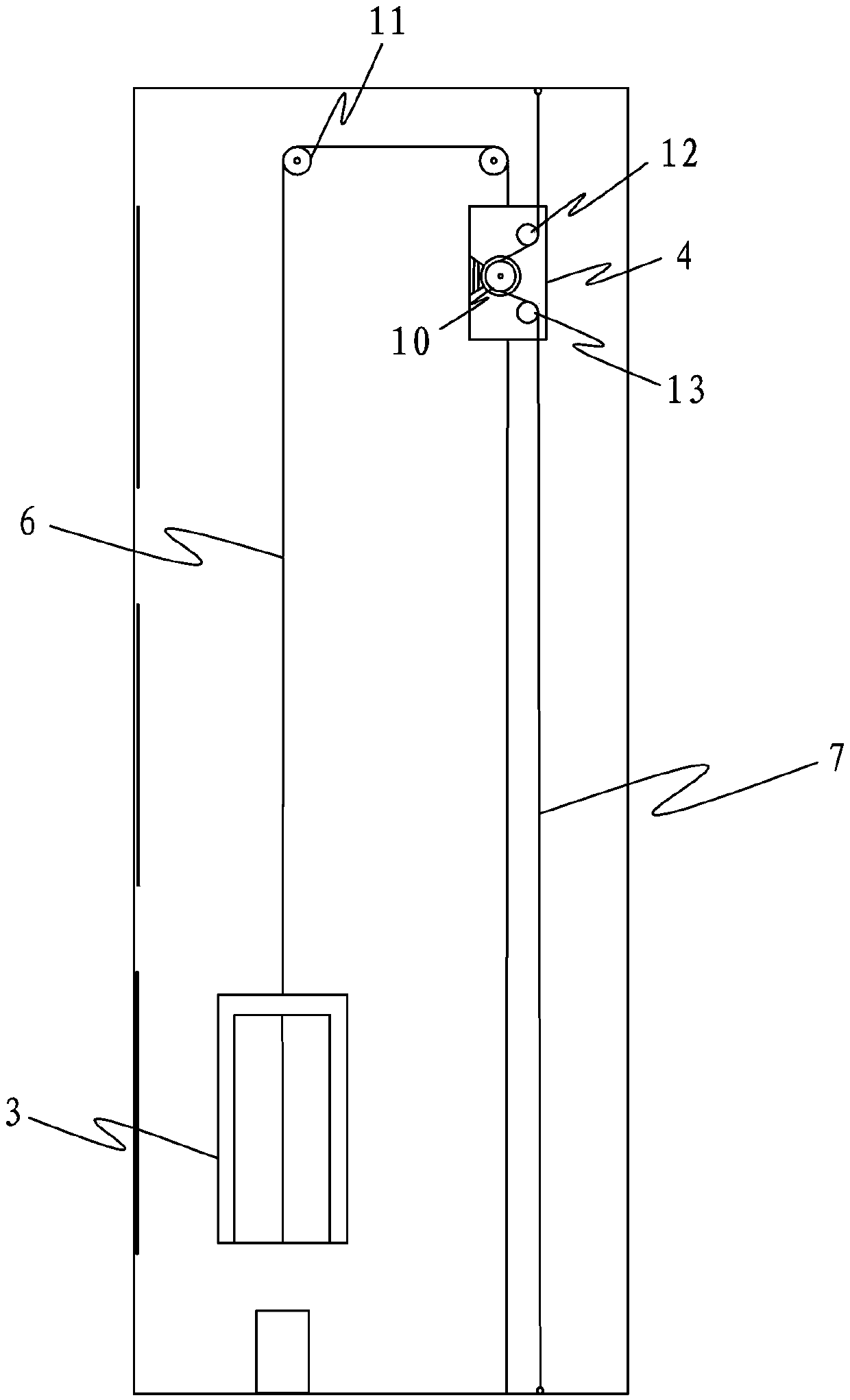
[0013] refer to figure 2 , the drive structure of a kind of elevator that the present invention provides, comprises car 3 and counterweight box 4, and the steel cable 6 that leads upwards from the top of car 3 passes through two turning wheels 11 in turn and is connected downwards to the top of counterweight box 4, The counterweight box 4 is provided with a drive motor and a traction wheel 10 connected to the drive motor, and the counterweight box 4 is also provided with an upper guide wheel 12 above the traction wheel 10 and a lower guide wheel 13 below the traction wheel 10 , the upper guide pulley 12 and the lower guide pulley 13 are located on the same side of the traction pulley 10, and after a transmission strip 7 passes through the upper guide pulley 12, the traction pulley 10 and the lower guide pulley 13 in turn, its upper end is fixed on the top of the elevator shaft, and its lower end Fixed at the bottom of the elevator shaft. When the elevator is working, the tra...


PUM


Abstract

The invention discloses a novel driving structure of an elevator. The novel driving structure comprises a driving motor, a dragging wheel connected with the driving motor, a lift car and a counter weight box. The driving motor and the dragging wheel are arranged in the counter weight box, and a steel cable led out from the top of the lift car upwards passes through two steering wheels sequentially to be connected with the top of the counter weight box. A transmission strip passes through the dragging wheel in the counter weight box, the upper end of the transmission strip is fixed on the top of an elevator shaft, the lower end of the transmission strip is fixed at the bottom of the elevator shaft, and the dragging wheel drives the counter weight box to move vertically along the transmission strip. The novel driving structure solves the installing problem of the driving motor and the dragging wheel and saves installing space. Simultaneously the driving motor and the dragging wheel serve as weights in the counter weight box, weights required to be configured are effectively reduced, and the cost is reduced.

Description

technical field [0001] The invention relates to a driving device, in particular to a driving structure of an elevator. Background technique [0002] refer to figure 1 , the figure shows the driving connection structure usually used by traditional elevators. A fixed pulley 1 is arranged on the top of the elevator shaft. The movable pulley 2 on both sides below the pulley 1 is hung with a car 3 and a counterweight box 4 respectively, and a weight 5 is arranged in the counterweight box 4 . In the above connection structure, the fixed pulley 1 is a traction pulley, and a driving motor is arranged beside the fixed pulley 1, and the driving motor drives the fixed pulley 1 to rotate, thereby driving the car 3 to rise or fall, and the movement status of the counterweight box 4 is the same as that of the car 3. on the contrary. [0003] The driving connection structure adopted by traditional elevators has the following disadvantages: one is the installation problem of the fixed pu...

Claims


Application Information

Patent Timeline
Patent Type & Authority Patents(China)
IPC IPC(8): B66B11/08B66B7/02
Inventor 邓之江
Owner 江门市蒙德电气股份有限公司
Why Eureka
Try Eureka