Wire transmission structure, surgical instrument and surgical robot

A technology of wire transmission and drive shaft, applied in the field of surgical instruments, can solve the problems of large occupied space and complex transmission structure, etc.

Active Publication Date: 2022-05-31
SHANGHAI MICROPORT MEDBOT (GRP) CO LTD
View PDF4 Cites 0 Cited by
  • Summary
  • Abstract
  • Description
  • Claims
  • Application Information

AI Technical Summary

Problems solved by technology

[0004] The purpose of the present invention is to provide a wire transmission structure, a surgical instrument and a surgical robot to solve one or more of the problems of the existing surgical instruments, such as complex transmission structure and large space occupation.

Method used


Image

  • Wire transmission structure, surgical instrument and surgical robot
  • Wire transmission structure, surgical instrument and surgical robot
  • Wire transmission structure, surgical instrument and surgical robot

Examples


Embodiment 1

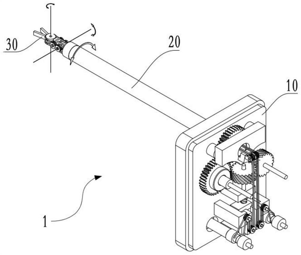
[0123] As shown in FIG. 1, a first embodiment of the present invention provides a surgical instrument, which includes: a wire transmission structure 10, an instrument rod 20

[0124] The following describes the wire transmission structure 10 provided by the embodiment of the present invention with reference to FIGS. 2 to 8 . wire transmission structure

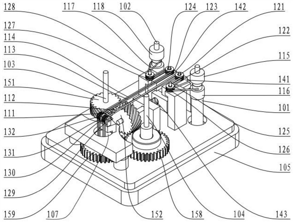
[0125] Wherein, the first drive shaft 101, the second drive shaft 102 and the third drive shaft 103 are respectively rotatably arranged in

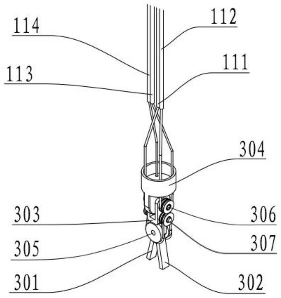
[0126] The second traction body group includes a third traction body 113 and a fourth traction body 114. The third traction body 113 has a

[0127] The first guide member is used to change the extension direction of the first traction body group, and the second guide member is used to change the extension direction of the first traction body group.

[0128] The third guide member and the fourth guide member are both arranged on the base 105. Wherein, the third guide is relative to the first ...

Embodiment 2

Again, only different points will be described below.

[0153] Please refer to FIG. 9, which is a schematic diagram of the transmission of the surgical instrument provided in the second embodiment of the present invention.

[0154] In the second embodiment, the transmission mode between the third drive shaft 103 and the transmission rod 143 is different from that in the first embodiment.

Embodiment 3

[0156] The wire transmission structure and the surgical instrument of the third embodiment of the present invention are basically the same as the first embodiment, and the same parts are not

[0158] In the third embodiment, the setting form of the transmission rod 143 is different from that in the first embodiment. Specifically, as shown in Figure 10 and Figure 11

[0159] Further, the wire transmission structure also includes a first transmission assembly, and the first transmission assembly includes a first tooth

[0160] Further, the transmission ratio of the first gear 153 and the second gear 154 is the same as the second external thread segment

[0162] In some alternative embodiments, the wire transmission structure further includes a rotating member, a first transmission member, and a second transmission member


PUM


Abstract

The invention provides a wire transmission structure, a surgical instrument and a surgical robot. The wire transmission structure includes a base, a first drive shaft, a second drive shaft, a third drive shaft, a first traction body group, a second traction body group, a A guide piece, a second guide piece, a third guide piece and a fourth guide piece; the base has a reference plane; each traction body group includes two traction bodies connected to a drive shaft, through which the drive shaft The rotation of the device can drive the corresponding two traction bodies to move in opposite directions, so as to drive a joint movement of the end assembly of the instrument respectively. Furthermore, the first traction body group and the second traction body group are taken as a whole, and through the action of the first guide member and the second guide member, they can drive the movement of the third joint of the end assembly of the instrument. Thus, the movement of the three joints of the end assembly of the instrument is driven by the four traction bodies, the transmission structure is simple, the space occupied is small, and the transmission efficiency is improved.

Description

Wire transmission structure, surgical instruments and surgical robots technical field [0001] The present invention relates to the field of surgical instruments, in particular to a wire transmission structure, surgical instruments and surgical robots. Background technique In recent years, with the application and development of robot-related technology, especially the development of computing technology, medical surgical machines The role of robotics in clinical practice has received more and more attention. Among them, the minimally invasive surgical robotic system can be The treatment method reduces the physical labor of the doctor during the operation, and at the same time achieves the purpose of precise operation, so that the patient has less trauma and loss of life. Less blood, less postoperative infection, faster postoperative recovery. The design of surgical instruments for surgical robots directly determines the micro-traumatic hand. Whether the surgical rob...

Claims


Application Information

Patent Timeline
Patent Type & Authority Patents(China)
IPC IPC(8): A61B34/30F16H37/12
CPCA61B34/30A61B34/70F16H37/12
Inventor 何裕源蒋友坤何超
Owner SHANGHAI MICROPORT MEDBOT (GRP) CO LTD
Why Eureka
Try Eureka