Fan and impeller thereof

A technology of fan blades and fans, which is applied to parts of pumping devices for elastic fluids, non-variable pumps, pump devices, etc., which can solve the problems of poor efficiency, reduce fan load and power consumption, etc.

Inactive Publication Date: 2007-11-28
DELTA ELECTRONICS INC
View PDF0 Cites 7 Cited by
  • Summary
  • Abstract
  • Description
  • Claims
  • Application Information

AI Technical Summary

Problems solved by technology

[0006] Therefore, in order to solve the above problems, the present invention proposes a fan and its impeller. By reducing the installation angle of the fan blades, the load and power consumption of the fan can be effectively reduced, thereby improving the overall efficiency of the fan and improving the disadvantages of poor efficiency of traditional fans.

Method used


Image

  • Fan and impeller thereof
  • Fan and impeller thereof
  • Fan and impeller thereof

Examples


Embodiment Construction

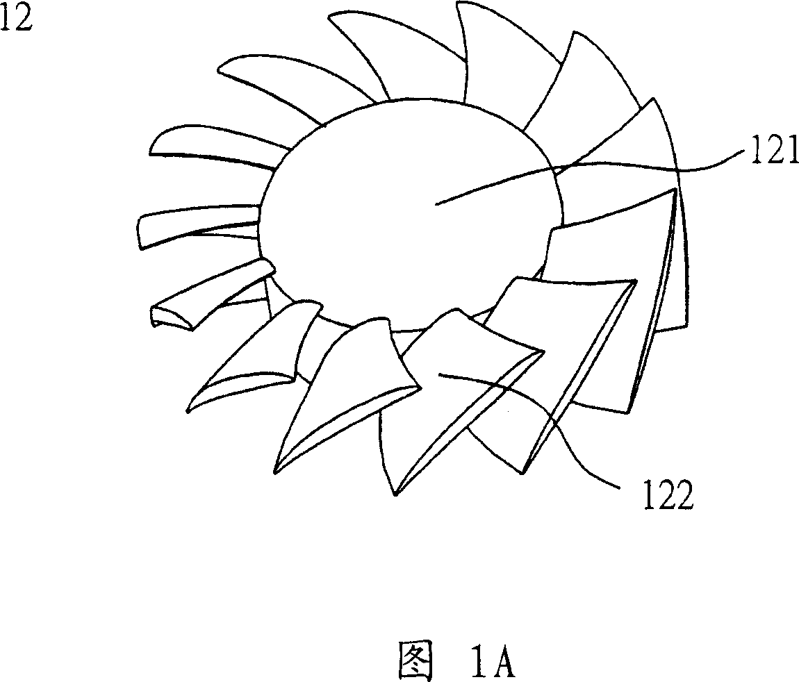
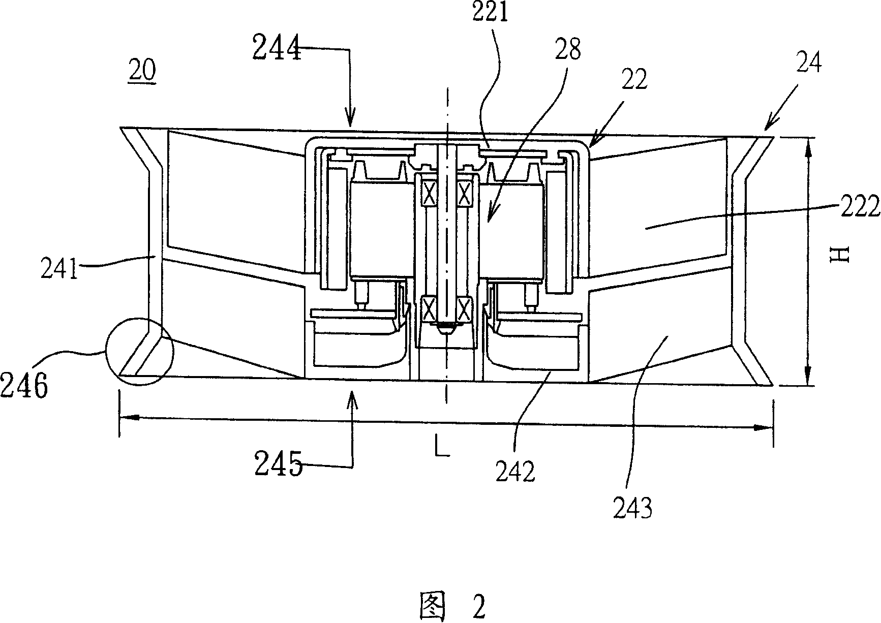
[0026] Please refer to FIG. 2 , which is a schematic cross-sectional view of a fan according to a preferred embodiment of the present invention. The fan 20 of the present invention is, for example, an axial fan, including a fan frame 24 , an impeller 22 , and a motor 28 . The fan frame 24 has a frame body 241 , a base 242 and at least one support member 243 , and the base 242 is connected to the frame body 241 through the support member 243 . The impeller 22 is disposed on the base 242 , and the impeller 22 includes a hub 221 and a plurality of fan blades 222 , and the plurality of fan blades 222 are disposed around the hub 221 . The motor 28 is connected with the impeller 22 and drives the impeller 22 to rotate.

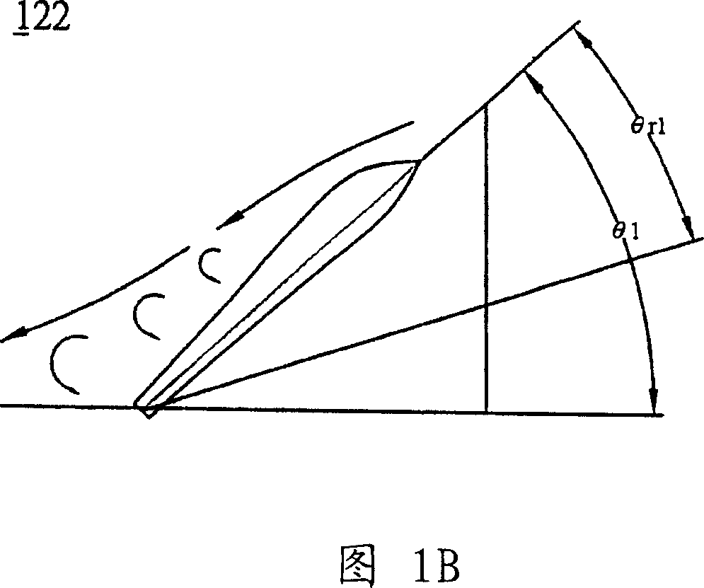
[0027] In order to improve the existing defect that the fan blades 222 are installed at an excessively large angle, the angle of the airflow entering the fan blades is too large and the airflow stripping phenomenon occurs, resulting in a large fan load and power co...


PUM


Abstract

The invention discloses a fan, comprising a fan frame, an impeller and a motor. The fan frame comprises a frame body, a base foundation and at least a support part. The base foundation is connected by the support part and the frame body. The impeller is set on the base foundation and comprises a hub and multiple fan leaves, which are set round the hub. The motor is connected with the impeller and drives the impeller rotate. Thereinto each fan leaf is connected on hub with a presetting installing angle and the presetting angle is from 22.5 degrees to 36 degrees.

Description

technical field [0001] The invention relates to a fan and its impeller, in particular to a high-efficiency and low-noise fan and its impeller. Background technique [0002] With the continuous improvement of the performance of electronic devices, cooling devices or cooling systems have become one of the indispensable equipment in current electronic devices, because if the heat energy generated by electronic devices is not dissipated properly, the performance will deteriorate at least, and the serious It may cause burning of the electronic device. Heat sinks are even more important for microelectronic components (such as integrated circuits, integrated circuits), because with the increase in integration and the advancement of packaging technology, the area of ​​integrated circuits is continuously shrinking, and the accumulated per unit area The heat energy is relatively higher, so heat dissipation devices with high heat dissipation efficiency have been actively researched an...

Claims


Application Information

Patent Timeline
IPC IPC(8): F04D29/38F04D29/52F04D29/54F04D25/08
Inventor 李金鸿李嵩蔚黄文喜
Owner DELTA ELECTRONICS INC
Why Eureka
Try Eureka