Wavelength conversion element and light source module

A wavelength conversion and component technology, applied in the direction of electrical components, optics, semiconductor devices, etc., to achieve the effect of slowing down the load power, size and weight reduction

Pending Publication Date: 2022-02-22
DELTA ELECTRONICS INC
View PDF8 Cites 1 Cited by
  • Summary
  • Abstract
  • Description
  • Claims
  • Application Information

AI Technical Summary

Problems solved by technology

The substrate is configured to rotate about an axis

Method used


Image

  • Wavelength conversion element and light source module
  • Wavelength conversion element and light source module
  • Wavelength conversion element and light source module

Examples


Embodiment Construction

[0041] A number of embodiments of the present invention will be disclosed in the following figures. For the sake of clarity, many practical details will be described together in the following description. It should be understood, however, that these practical details should not be used to limit the invention. That is, in some embodiments of the present invention, these practical details are unnecessary. In addition, for the sake of simplifying the drawings, some existing conventional structures and components will be shown in a simple schematic manner in the drawings.

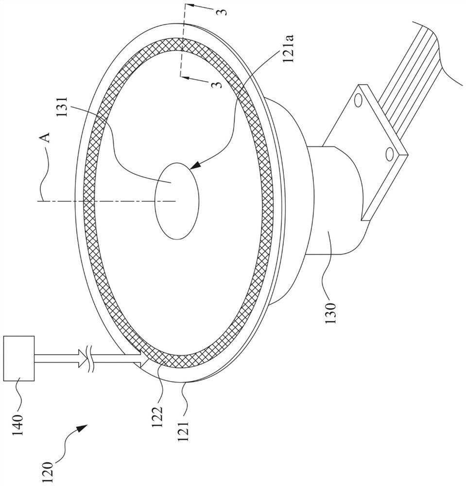
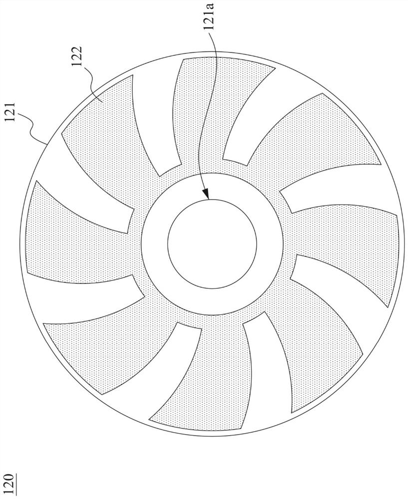
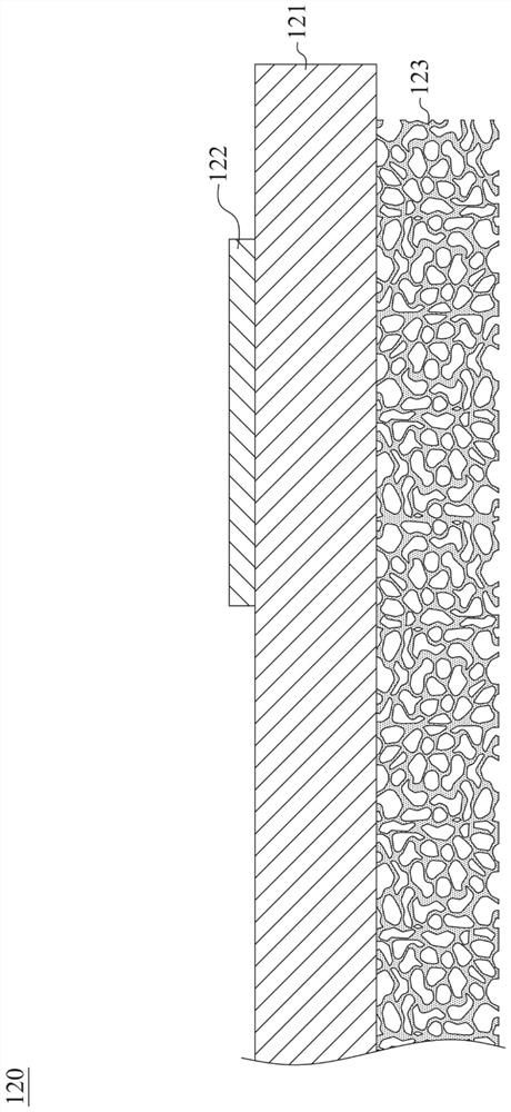
[0042] Please refer to figure 1 . figure 1 The light source module used in the projection device includes a wavelength conversion element 120 , a driving unit 130 and a light source 140 . The wavelength conversion element 120 includes a substrate 121 . The base plate 121 has a shaft hole 121a. The driving unit 130 is connected to the wavelength conversion element 120 and is configured to drive the waveleng...


PUM

PropertyMeasurementUnit
surface roughnessaaaaaaaaaa
thicknessaaaaaaaaaa

Abstract

A wavelength conversion element comprises a substrate, a fluorescent powder layer and a through-hole blade. The substrate is configured to rotate based on an axis. The fluorescent powder layer is arranged on the substrate. The through-hole blade is disposed on the substrate, and has a pore density of between 10 ppi and 500 ppi, or has a volume porosity of between 5% and 95%.

Description

technical field [0001] The invention relates to a wavelength conversion element and a light source module Background technique [0002] In recent years, optical projectors have been used in many fields, and the range of applications is expanding day by day, from consumer products to high-tech equipment. Various optical projectors are also widely used in schools, homes and commercial occasions to amplify the display pattern provided by the signal source and display it on the projection screen. [0003] For the light source configuration of the optical projector, it can be driven by a solid-state laser light source to make the fluorescent material emit light. In this regard, the fluorescent material can be coated on the wheel, and the motor is used to drive the wheel to make it rotate at a high speed, so as to reduce the energy of the laser light source received by the fluorescent material in a unit time, thereby achieving the purpose of heat dissipation. However, as the bri...

Claims


Application Information

Patent Timeline
Patent Type & Authority Applications(China)
IPC IPC(8): G03B21/20
CPCG03B21/204G03B21/14G03B21/16H01L33/504H01L33/505H01L2933/0041
Inventor 周彦伊李日琪黄文政
Owner DELTA ELECTRONICS INC
Why Eureka
Try Eureka