Exhaust device

A technology of exhaust equipment and exhaust machine, which is applied in the manufacture of electrical components, discharge tubes/lamps, and cold cathodes. Effect of improving exhaust efficiency

Inactive Publication Date: 2007-11-28
GIGNO TECH CO LTD
View PDF0 Cites 0 Cited by
  • Summary
  • Abstract
  • Description
  • Claims
  • Application Information

AI Technical Summary

Problems solved by technology

[0011] This shows that the above-mentioned existing exhaust equipment obviously still has inconvenience and defects in structure and use, and needs to be further improved urgently.
In order to solve the above-mentioned problems, the relevant manufacturers have tried their best to find a solution, but no suitable design has been developed for a long time, and the general products do not have a suitable structure to solve the above-mentioned problems. This is obviously related. The problem that the industry is eager to solve

Method used


Image

  • Exhaust device
  • Exhaust device
  • Exhaust device

Examples


Embodiment Construction

[0052] In order to further explain the technical means and effects of the present invention to achieve the intended purpose of the invention, the specific implementation, structure, characteristics and effects of the exhaust equipment proposed according to the present invention will be described below in conjunction with the accompanying drawings and preferred embodiments. Details are as follows.

[0053] An exhaust device according to a preferred embodiment of the present invention will be described below with reference to related drawings, wherein the same elements will be described with the same reference symbols.

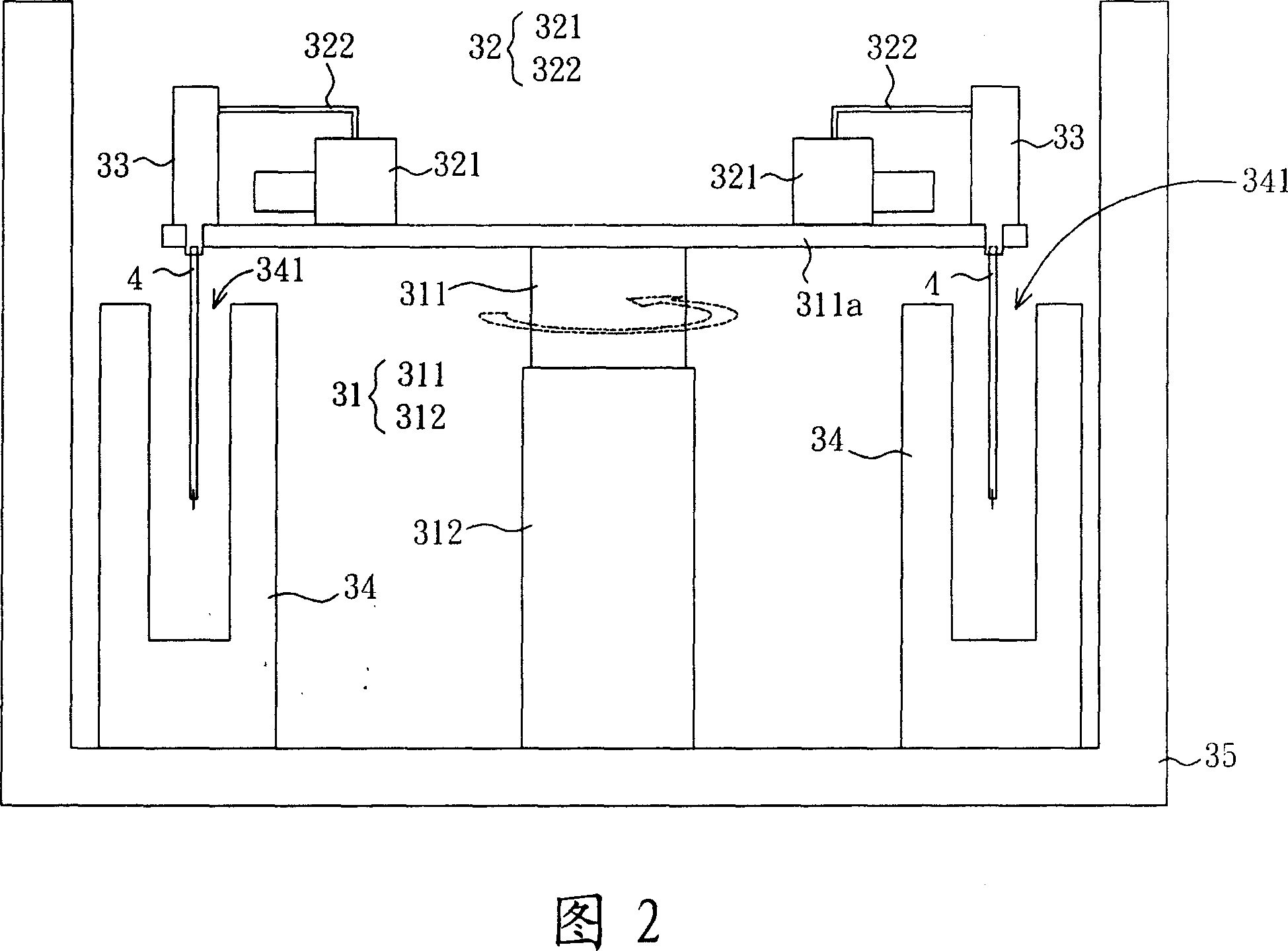
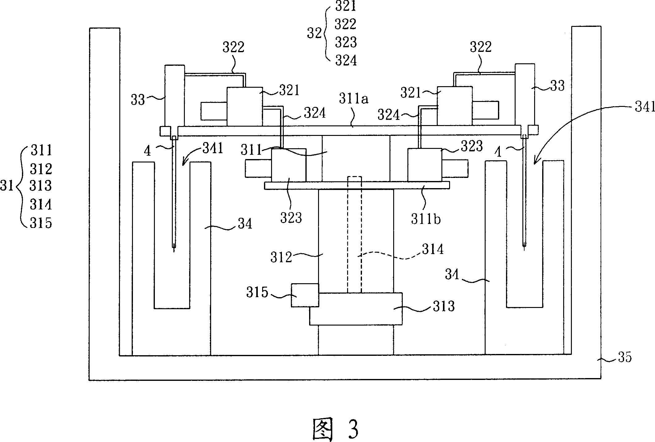
[0054] Please refer to FIG. 2 , which is a partial side sectional view of an exhaust device according to a preferred embodiment of the present invention. An exhaust device according to a preferred embodiment of the present invention includes a rotating shaft 31 , an exhaust unit 32 and an exhaust head 33 . In this embodiment, the exhaust device is an exhaust de...


PUM


Abstract

The invention discloses an exhausting equipment, which comprises the following parts: rotary shaft, exhausting aggregate and exhausting head, wherein the rotary shaft possesses first shaft part and second shaft part with rotatable first shaft part corresponding to the second shaft part; the exhausting aggregate is set at the first shaft part of the rotary shaft; the exhaust head is connected with the exhaust aggregate; when the first shaft part rotates corresponding to the second shaft part, the exhausting aggregate also rotates to save traditional central valve, in order avoid oil gas reflux pollution due to the central valve; the exhausting aggregate is set at the first shaft part directly to reduces the distance between the exhausting aggregate and the exhausting-waiting element effectively, which improves the exhausting efficiency obviously.

Description

technical field [0001] The invention relates to an exhaust device, in particular to an exhaust device for a lamp tube. Background technique [0002] In the production process of the lamp tube, the exhaust equipment is one of the very important equipment, its main purpose is to heat the lamp tube, vacuumize, clean, fill the gas and seal the process. [0003] Among them, the vacuum system is one of the core systems of the exhaust equipment. Generally speaking, the vacuum pump (pump) of the vacuum system is arranged outside the main body of the exhaust equipment, and is connected between the vacuum pump and the exhaust head through a vacuum pipeline. The vacuum process of the lamp tube must be done step by step, so multiple vacuuming procedures are required. In order to make the lamp tube pass through the vacuuming procedures of each vacuum pump in sequence, a center valve (Center Valve) must be designed between the vacuum pump and the exhaust head. ), so that the lamp can be ...

Claims


Application Information

Patent Timeline
Patent Type & Authority Applications(China)
IPC IPC(8): H01J9/38H01K3/24
Inventor 林峰立
Owner GIGNO TECH CO LTD
Why Eureka
Try Eureka