Exhaust apparatus

A technology of exhaust equipment and exhaust machine, applied in the direction of electric tube/lamp exhaust, electrical components, etc., can solve the problems of reduced exhaust efficiency, oil and gas backflow, production line shutdown, etc., to avoid oil and gas backflow pollution, exhaust gas, etc. Efficiency improvement, the effect of improving efficiency

Inactive Publication Date: 2008-03-19
GIGNO TECH CO LTD
View PDF0 Cites 0 Cited by
  • Summary
  • Abstract
  • Description
  • Claims
  • Application Information

AI Technical Summary

Problems solved by technology

[0009] Based on the above, in the existing exhaust equipment, since the vacuum pump is arranged outside the main body of the exhaust equipment, it requires the configuration of a long-distance vacuum pipeline, resulting in a decrease in exhaust efficiency, or a larger-scale vacuum pump is required to make up for the loss of efficiency
In addition, because the central valve is designed with oil seal, when the exhaust equipment is in operation, the rotating action will cause part of the oil and gas to flow back, which will cause oil and gas to pollute the quality of the product
Moreover, the contact surface between the rotating part and the fixed part of the central valve is processed by precision polishing. If dust or foreign matter enters, it will cause scratches on the contact surface and cause air leakage, which will cause the shutdown of the production line.

Method used


Image

  • Exhaust apparatus
  • Exhaust apparatus
  • Exhaust apparatus

Examples


Embodiment Construction

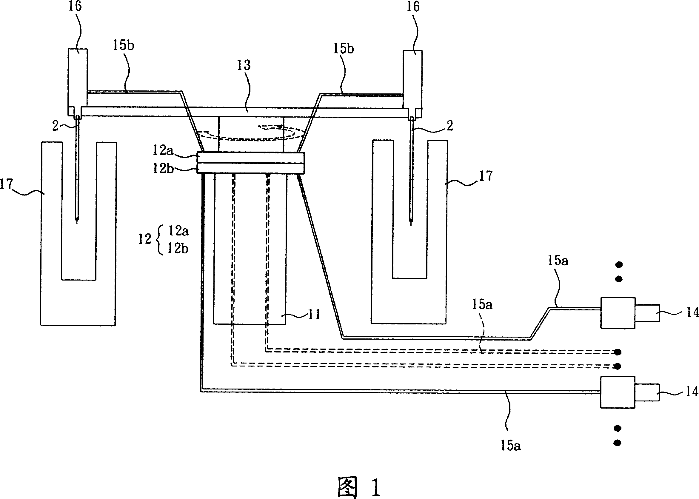
[0059] In order to further explain the technical means and effects of the present invention to achieve the intended purpose of the invention, the specific implementation, structure, characteristics and effects of the exhaust equipment proposed according to the present invention will be described below in conjunction with the accompanying drawings and preferred embodiments. Details are as follows.

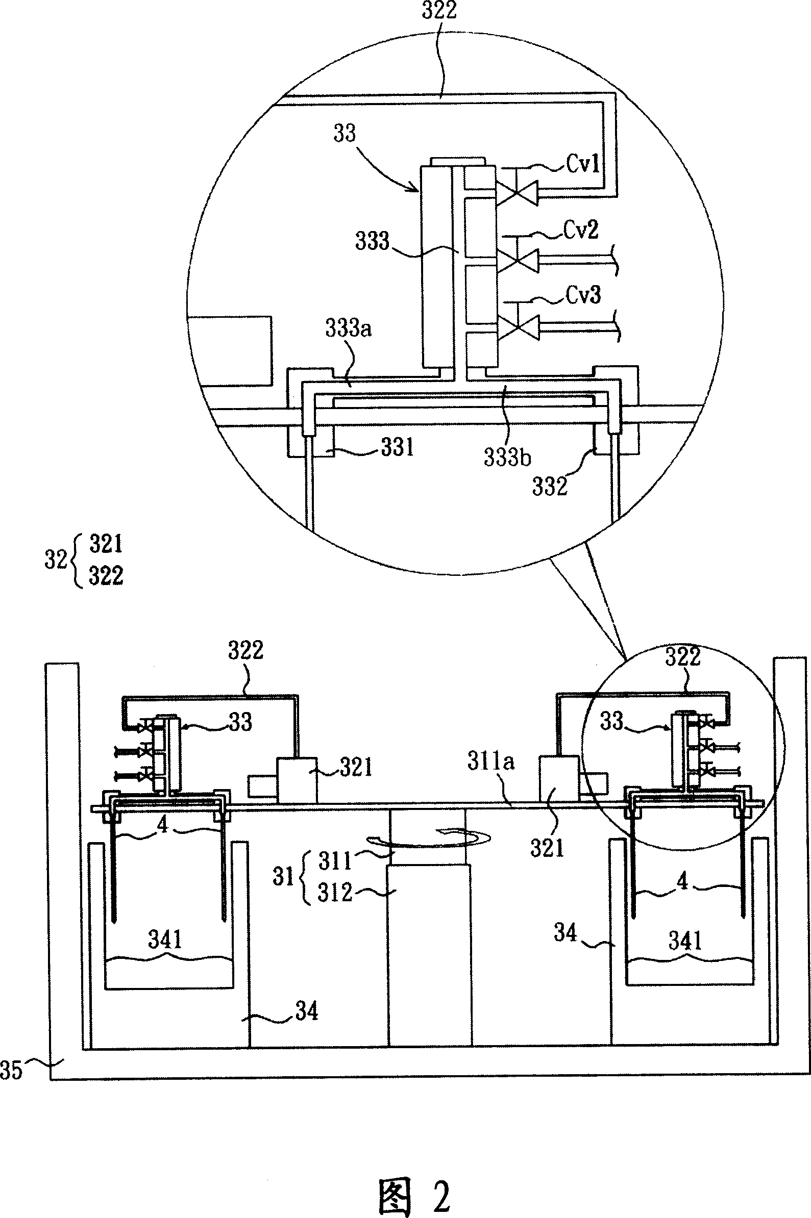
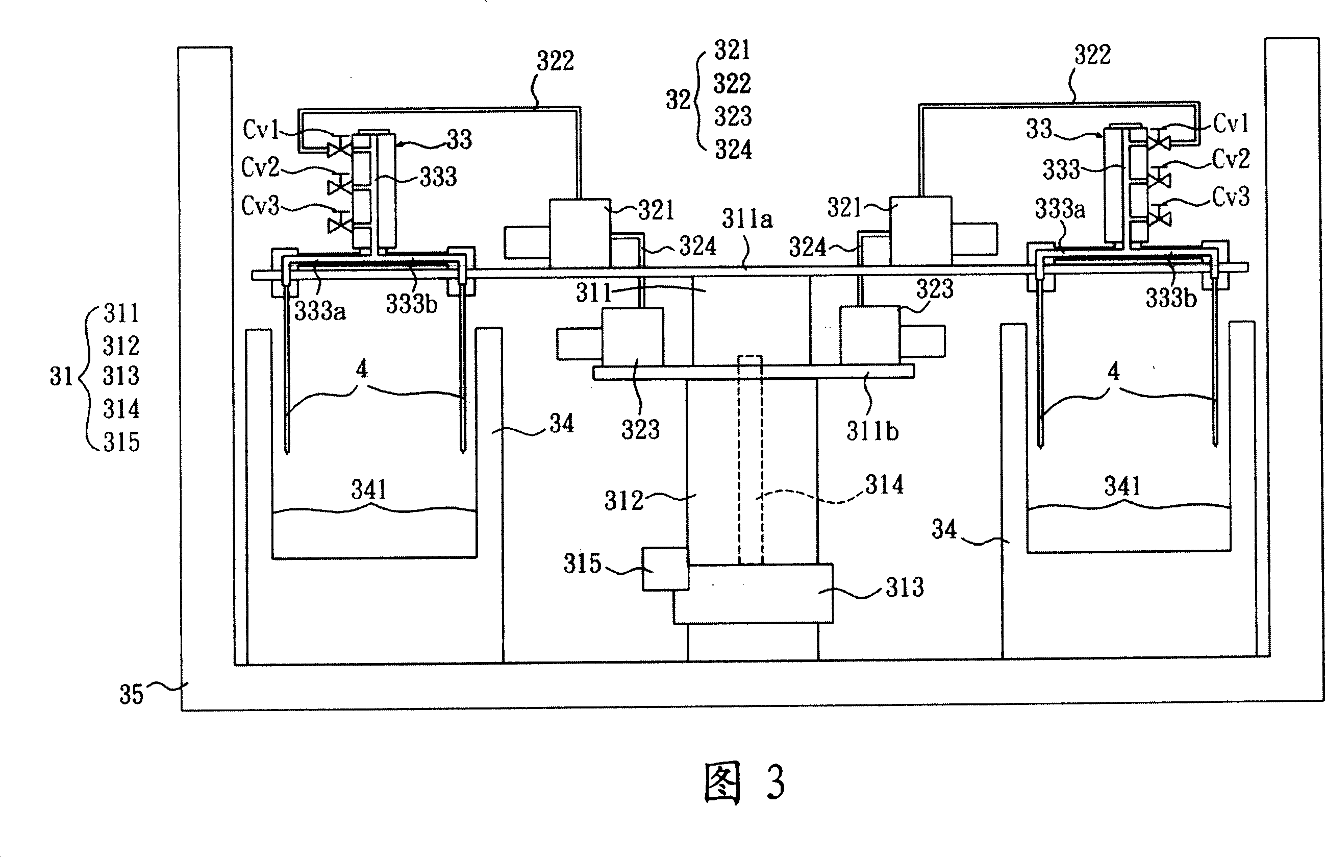
[0060] Please refer to FIG. 2 , which is a partial side sectional view of an exhaust device according to a preferred embodiment of the present invention. An exhaust device according to a preferred embodiment of the present invention includes a rotating shaft 31 , an exhaust unit 32 and an exhaust head 33 . In this embodiment, the exhaust device is an exhaust device for a lamp tube 4, wherein the lamp tube 4 can be a hot cathode lamp tube, a cold cathode lamp tube or other lamp tubes requiring an exhaust process.

[0061] The rotating shaft 31 includes a first shaft portion 311 and ...


PUM


Abstract

Gas exhaust equipment is provided, which comprises a rotating shaft, a gas exhaust assembly and a gas exhaust head. The rotating shaft has a first shaft portion and a second shaft portion, wherein the first shaft portion rotates with respect to the second shaft portion. The gas exhauster assembly is arranged on the first shaft portion of the rotating shaft and has a first conduit. The gas exhaust head at least has a first retaining portion and a second retaining portion, which are connected with the first conduit of the gas exhauster assembly. The inventive gas exhaust equipment can increase the gas exhaustion efficiency.

Description

technical field [0001] The invention relates to an exhaust device, in particular to an exhaust device for a lamp tube. Background technique [0002] In the manufacturing process of the lamp tube, the exhaust equipment is a very important equipment. Its main purpose is to heat, vacuumize, clean, fill the gas and seal the lamp tube. [0003] Among them, the vacuum system is one of the core systems of the exhaust equipment. Generally speaking, the vacuum pump (pump) of the vacuum system is arranged outside the main body of the exhaust equipment, and is connected between the vacuum pump and the exhaust head through a vacuum pipeline. The vacuum process of the lamp tube must be done step by step, so multiple vacuuming procedures are required, and in order for the lamp tube to pass through the vacuuming procedures of each vacuum pump in sequence, a center valve (Center Valve) must be designed between the vacuum pump and the exhaust head. ), so that the lamp can be vacuumed smooth...

Claims


Application Information

Patent Timeline
IPC IPC(8): H01J9/385H01K3/24
Inventor 林峰立
Owner GIGNO TECH CO LTD
Why Eureka
Try Eureka