Visual inspection device and method

A visual inspection device and technology for visual inspection, which are applied to measurement devices, optical devices, instruments, etc., can solve the problems of large size, increase in the number of parts, and decrease in reliability, and achieve the effect of a simple mechanism

Inactive Publication Date: 2007-11-28
PANASONIC CORP
View PDF6 Cites 15 Cited by
  • Summary
  • Abstract
  • Description
  • Claims
  • Application Information

AI Technical Summary

Problems solved by technology

[0019] However, in the existing structure, XY scanning and Z scanning are independently implemented. If XY scanning and Z scanning are to be realized at the same time in order to...

Method used


Image

  • Visual inspection device and method
  • Visual inspection device and method
  • Visual inspection device and method

Examples


no. 1 approach 》

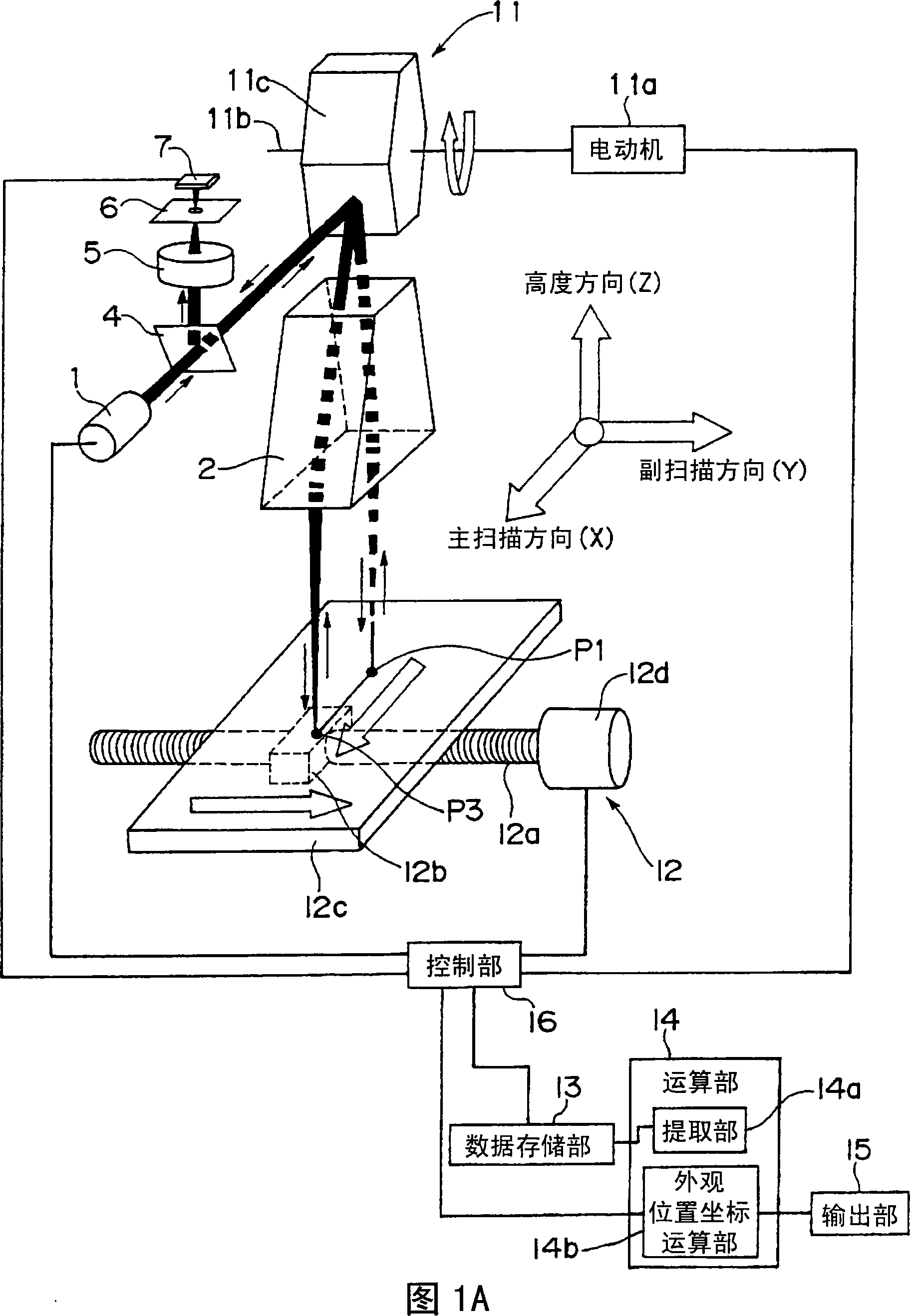
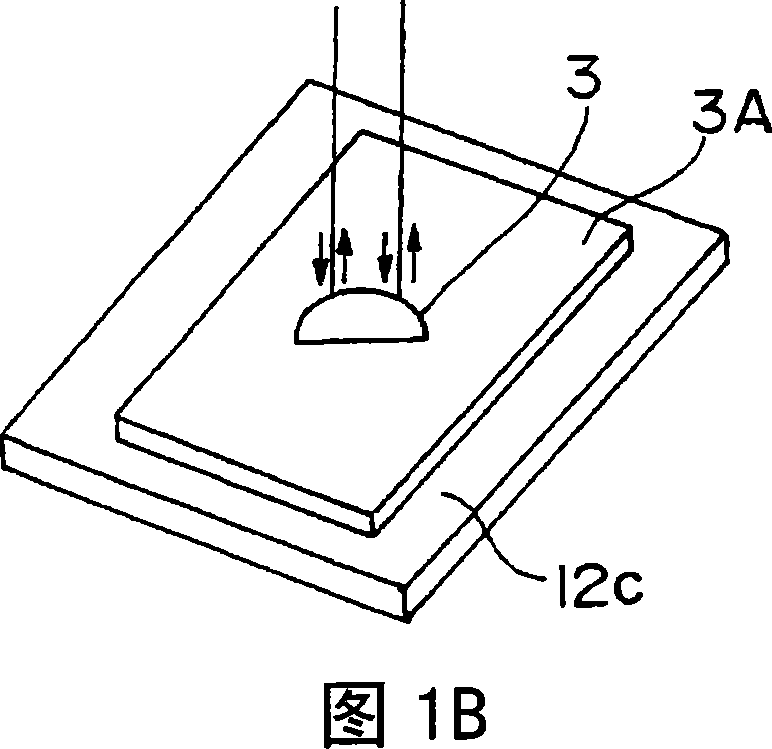
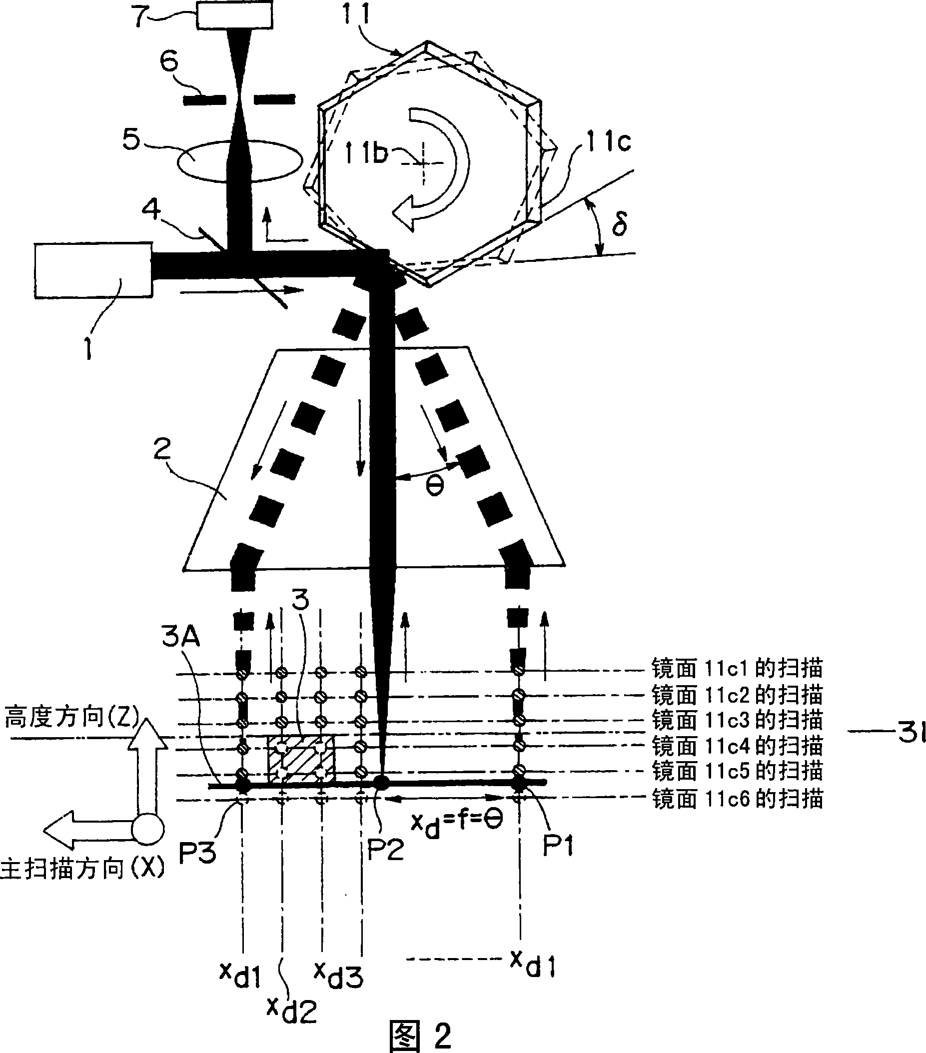
[0064] 1A is a schematic perspective view showing the configuration related to the optical system and the mechanical system of the visual inspection device in the first embodiment of the present invention, and FIG. 1B is a partially enlarged perspective view of FIG. 1A showing the inspection object 3 . In addition, FIG. 2 is a schematic diagram of the same optical system viewed from the sub-scanning direction.

[0065] First, the basic structure of the visual inspection device in the first embodiment of the present invention will be described using FIGS. 1A and 1B .

[0066] The appearance inspection apparatus in the first embodiment of the present invention includes: a light source 1, a rotating polygon mirror 11, a motor 11a, a scanning condenser lens 2 constituting an example of an optical system for forming a focal point position, a light splitting mirror 4, a reflected light Condenser lens 5, shielding plate 6, photodetector 7, table transport device 12 as an example of i...

no. 2 approach 》

[0143] 9A is a schematic diagram of the configuration of the optical system of the visual inspection apparatus and method in the second embodiment of the present invention viewed from the sub-scanning direction Y. FIG. 9B is a schematic diagram of the configuration of the optical system of the visual inspection device in the second embodiment of the present invention viewed from the main scanning direction X. FIG.

[0144] The appearance inspection device and method according to the second embodiment of the present invention, as shown in FIGS. 9A and 9B , includes a method that does not tilt the optical axis of the scanning condenser lens 2 from a plane perpendicular to the rotation axis 11b of the rotating polygon mirror 11. The scanning condenser lens 2A is arranged parallel to the height direction Z at an angle β, and an example of an optical system for forming a focal point position is provided between the scanning condenser lens 2A and the object 3 to be inspected. 1. The...


PUM

PropertyMeasurementUnit
Thicknessaaaaaaaaaa

Abstract

A rotary polygon mirror (11) is constituted such that the condensing point of a scanning light flux is deviated in a sub-scanning direction (Y) as it rotates at an isogonal speed and an angle formed between the rotation axis (11b) and a mirror plane differs from one mirror plane to another, a condensing point position forming optical system (2, 17) is constituted such that the condensing point moves within an inspection range Zr in a height direction Z, and an object of inspection (3) is moved in a sub-scanning direction so that the condensing point deviated in the sub-scanning direction and the height direction in synchronization with the isogonal-speed rotation of the rotary polygon mirror is scanned linearly in the height direction of the object of inspection to complete XYZ scanning, whereby the positional coordinates of the appearance of the object of inspection are obtained by a confocal method to perform visual inspection.

Description

technical field [0001] The present invention relates to an apparatus and method for visual inspection of an object to be inspected. More specifically, it relates to a method for forming a focus position by passing light from a point source such as a laser (irradiation light) through a polygon mirror (hereinafter referred to as a rotating polygon mirror) and a scanning condenser lens. The optical system irradiates the object to be inspected and then scans it in a straight line, and the reflected light reflected by the object to be inspected is deflected (deflected) by the mirror surface of the rotating polygon mirror through the optical system for forming the focus position (episode reflected light: incident reflected light) The light intensity of light) is photoelectrically converted, and the position coordinates of the appearance are obtained according to the principle of the confocal method, thereby inspecting the appearance of the object to be inspected. [0002] In particu...

Claims


Application Information

Patent Timeline
IPC IPC(8): G01B11/24
CPCG01N21/8903G01B11/24G01B11/30
Inventor 小野裕司
Owner PANASONIC CORP
Why Eureka
Try Eureka