Pure dielectric antennas and related devices

A dielectric and antenna technology, applied in the direction of electrical short antennas, antennas, electrical components, etc., can solve problems such as radiation and leakage

Inactive Publication Date: 2007-11-28
ANTENOVA LTD
View PDF0 Cites 3 Cited by
  • Summary
  • Abstract
  • Description
  • Claims
  • Application Information

AI Technical Summary

Problems solved by technology

However, this guiding action is disadvantageous because considerable energy can leak through the rod wall and be radiated

Method used


Image

  • Pure dielectric antennas and related devices
  • Pure dielectric antennas and related devices
  • Pure dielectric antennas and related devices

Examples


Embodiment Construction

[0065] 1) Pure dielectric dipole antennas and other balanced antennas

[0066] A description of the basic technique will be made below using a purely dielectric dipole antenna of the first modification of the embodiment of the present invention as an example.

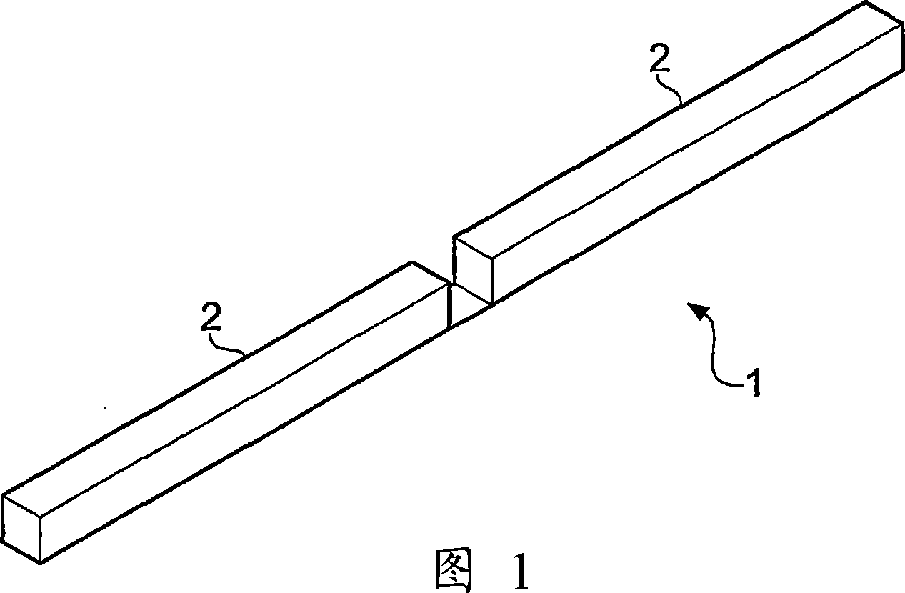
[0067] FIG. 1 shows a simulated ceramic dipole 1 in free space with a pair of collinear radiating arms 2 .

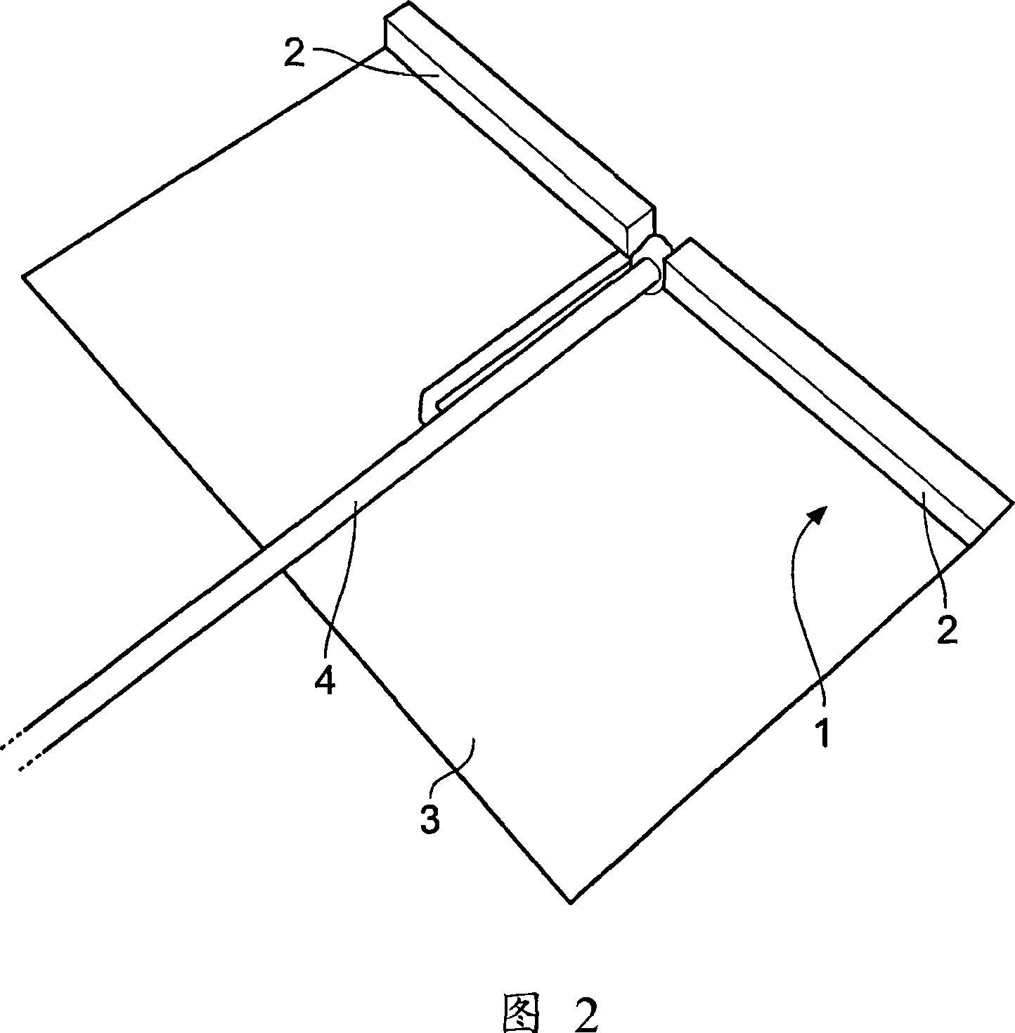
[0068] Figure 2 shows a practical realization of the concept shown in Figure 1, in the form of a dipole 1, comprising r ≈2.2) A pair of rectangular dielectric ceramic elements 2 mounted on a wire, substrate 3 with a microstrip balun 4.

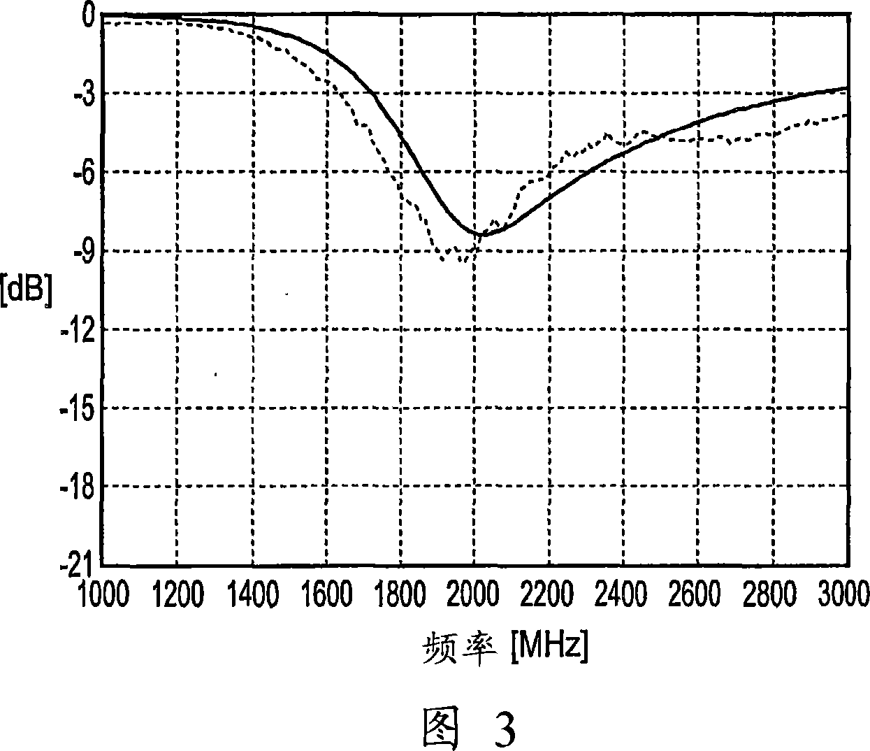
[0069] Figure 3 shows the calculated (solid line) and measured (dashed line) matched return loss for the embodiments of Figures 1 and 2, respectively, while Figure 4 shows the unmatched return loss.

[0070] For this antenna, it has been found that increasing the size will cause the resonant frequency to decrease in exactly the opposite proportion. Therefore, with a dielectric...


PUM


Abstract

There is disclosed an antenna device comprising an elongate dielectric radiating element having a longitudinal axis and a feeding mechanism for generating displacement currents in the dielectric radiating element. The radiating element is configured to support displacement current resonance modes parallel to the longitudinal axis but to inhibit displacement current resonance modes transverse to the longitudinal axis.

Description

[0001] The present invention relates to novel antennas particularly suitable for RF applications in which elongated substantially pure dielectric components support novel resonant modes. Background technique [0002] The applicant has developed a new antenna technology based on a substantially pure dielectric material, which is considered to be distinct from dielectric resonator antennas (DRA) and electrically conductive antennas. Electrically conductive antennas such as dipoles can be nearly infinitely thin if the conductivity is good enough, whereas the substantially pure dielectric antennas of embodiments of the present invention require a finite cross-section to radiate effectively. The DRA is a volume device that radiates like a cavity. If the DRA is made long and thin enough that transverse resonant modes are no longer possible (at frequencies of interest), it is not clear whether the DRA will become a purely dielectric antenna, as this topic has never been investigated ...

Claims


Application Information

Patent Timeline
Patent Type & Authority Applications(China)
IPC IPC(8): H01Q9/04H01Q9/36
CPCH01Q9/36H01Q9/0485H01Q9/04
Inventor 乔纳森·埃德西蒙·菲利普·金斯利史蒂文·格雷戈里·奥基夫塞普·萨里奥
Owner ANTENOVA LTD
Why Eureka
Try Eureka