Verschluss

A technology for zippers and zipper tapes, applied in the field of zippers, which can solve the problems of unintentional opening of the right and left edge parts, and achieve the effects of easy orientation, shortened manufacturing time, and simplified manufacturing process

Active Publication Date: 2007-12-05
YKK CORP
View PDF3 Cites 14 Cited by
  • Summary
  • Abstract
  • Description
  • Claims
  • Application Information

AI Technical Summary

Problems solved by technology

Therefore, if the slide fastener closed only by the magnetic force of a magnet is used for the fly of clothing, etc., when the user wears the clothing, it often happens that the right side edge portion and the left side edge portion are accidentally opened. Defects

Method used


Image

  • Verschluss
  • Verschluss
  • Verschluss

Examples


no. 1 example

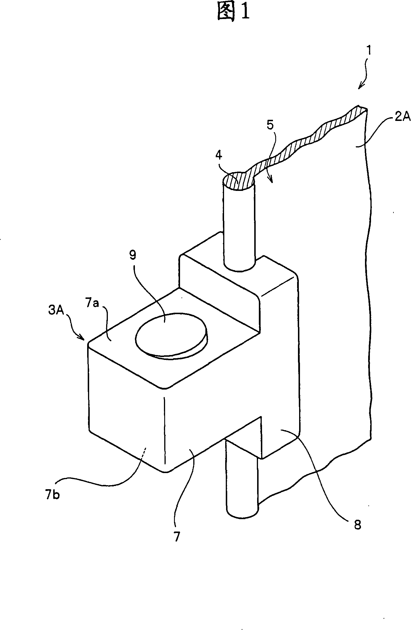
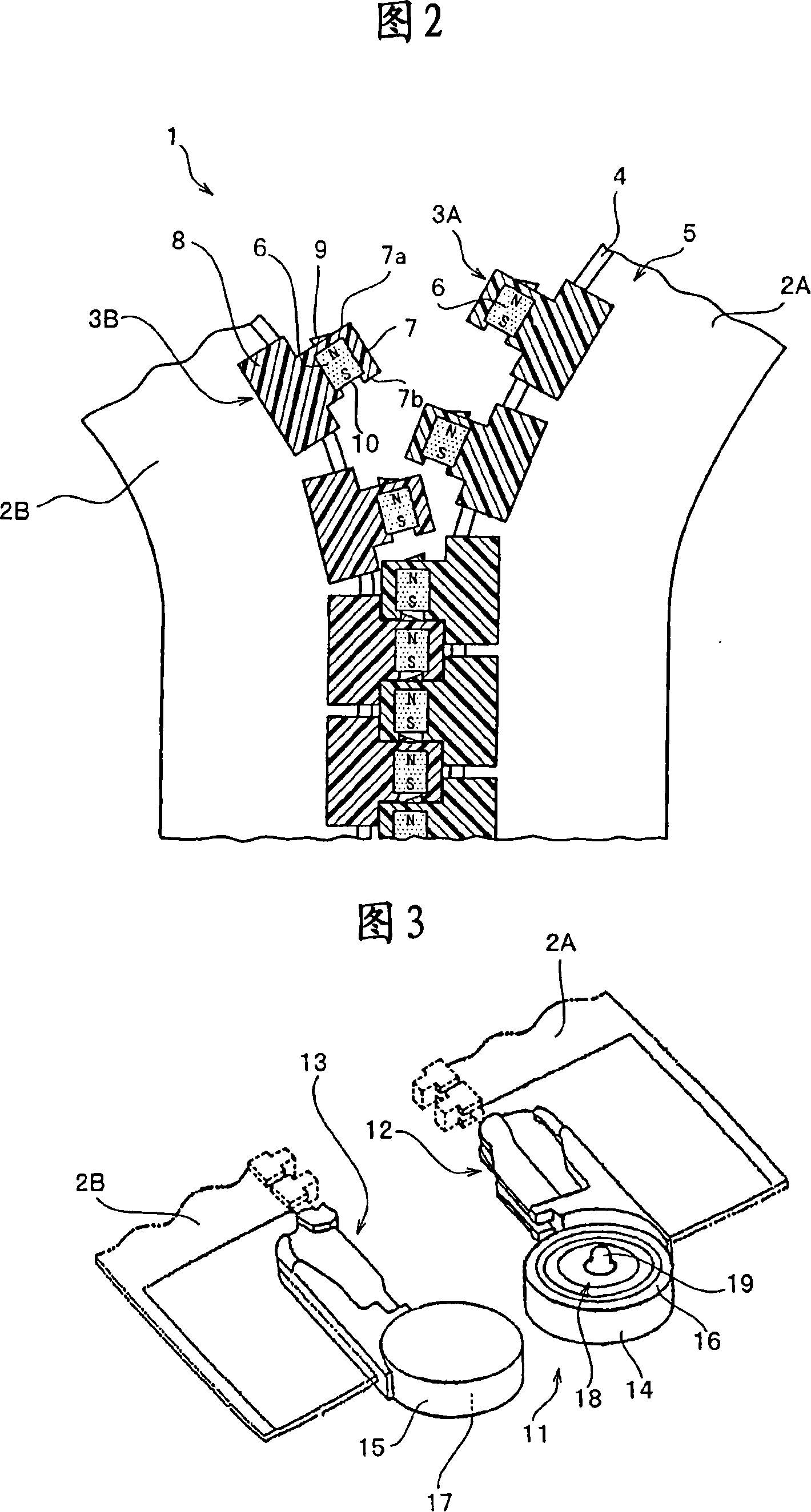
[0052] FIG. 1 is a perspective view showing a magnetic element of a slide fastener according to a first embodiment of the present invention. Fig. 2 is a front view of a part of the slide fastener according to the first embodiment, particularly showing the magnetic element in section. In the following description, in FIG. 1 , one direction (direction upward in the figure) along the longitudinal direction of the fastener tape is defined as the front, and the other direction (direction downward in the figure) is defined as the rear.

[0053] The slide fastener 1 of the first embodiment includes a pair of first and second fastener tapes 2A and 2B and a plurality of first and second magnetic elements 3A and 3B made of synthetic resin. The core part 4 is formed at the opposite side edges of the first fastener tape 2A and the second fastener tape 2B, and a plurality of first magnetic elements 3A and second magnetic elements 3B are formed at constant intervals along the first fastener...

no. 2 example

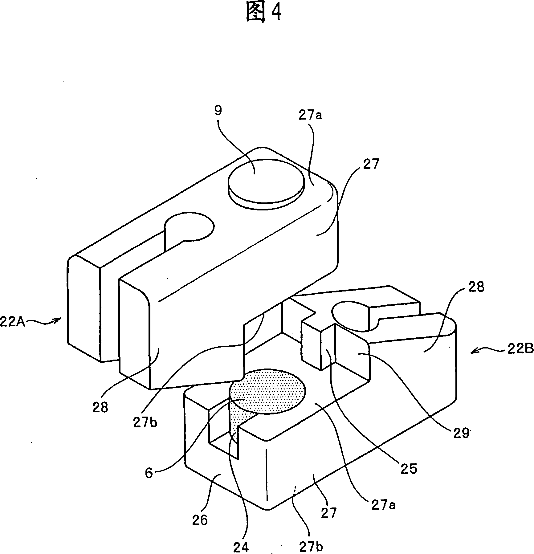
[0065] Next, a slide fastener according to a second embodiment of the present invention will be described. In the description of the second embodiment and the following, components having the same configuration as those of the first embodiment are denoted by the same reference numerals, and descriptions thereof are omitted. FIG. 4 is a perspective view showing a magnetic element of a slide fastener according to a second embodiment, and FIG. 5 is a front view showing a part of the slide fastener of the second embodiment.

[0066] The slide fastener 21 according to the second embodiment includes a pair of first fastener tape 2A and second fastener tape 2B and a plurality of element attachment edge portions 5 corresponding to the first fastener tape 2A and second fastener tape 2B arranged in a row at constant intervals. The first magnetic fastener element 22A and the second magnetic fastener element 22B are provided.

[0067] The first magnetic fastener element 22A and the secon...

no. 3 example

[0076] Next, a slide fastener according to a third embodiment of the present invention will be described. Fig. 8 is a perspective view showing a magnetic element of the slide fastener of the third embodiment. Fig. 9 is a front view showing a part of the slide fastener of the third embodiment. In FIG. 9 , the illustration of the fastener tape is omitted.

[0077] The slide fastener 31 of the third embodiment includes a pair of first and second fastener tapes and a plurality of first magnetic elements arranged in a row at constant intervals along the element attachment edge portions of the first and second fastener tapes. 32A and the second magnetic element 32B.

[0078] Each magnetic fastener element 32A, 32B includes a magnetic head portion 37 and a tooth leg portion 38 , wherein the magnet 6 is embedded in the head portion 37 . The magnet 6 is embedded in the first opposing surface 37a and the second opposing surface 37b of the dental bag portion 37, thereby exposing the f...


PUM


Abstract

A fastener wherein right and left side edge portions can be engaged using a magnetic force, and which can be applied preferably for plastic article such as clothes and further prevented from being opened carelessly even if a lateral pulling force is applied when right and left elements are engaged. In the fastener, a plurality of first and second magnetic elements(3A,3B) having magnetism are provided in lines on a pair of first and second fastener tapes(3A,3B), the first and second magnetic elements(3A,3B) are adsorbed to each other using a magnetic force, characterized in that the first and second magnetic elements have head portions(7), a leg portion(8), and engagement / disengagement portions(9,10) formed at the head portions and mechanically engaged with or disengaged from each other between the first and second magnetic elements(3A,3B), the first and second magnetic elements are respectively disposed at predetermined intervals, the magnetic elements(3A) of one fastener tape(2A)(3B) are adsorbed to spaces between the adjacent magnetic elements of the other fastener tape(2B), and the first and second magnetic elements(3A,3B) are engaged with each other alternately.

Description

technical field [0001] The present invention relates to a slide fastener for opening or closing a fly of clothes, and more particularly, to a slide fastener for attaching a magnetic element provided with magnetism by a magnet or the like to opposing element attachment edge portions of a pair of slide fastener tapes to engage the opposite right and left magnetic elements using the magnetic force of the magnetic elements. Background technique [0002] USP No. 4,399,595 discloses a zipper that utilizes the magnetic force of a magnet to open or close the front of a garment. In the slide fastener disclosed in USP No. 4,399,595, magnets are arranged at predetermined intervals on opposite side edge portions of a fly portion of clothing so that N poles and S poles alternately appear. By overlapping the front side of one side edge part with the back side of the other side edge part, the N pole and S pole of the magnet provided on the side edge part are magnetically attracted to each...

Claims


Application Information

Patent Timeline
Patent Type & Authority Applications(China)
IPC IPC(8): A44B19/04A44B19/06A44B99/00
CPCY10T24/2539Y10T24/32A44B19/08A45C13/1069A41F1/002A44D2203/00
Inventor 近藤祐司林亚己夫小泽贵敬三熊亮坂本绘里子大角美幸
Owner YKK CORP
Why Eureka
Try Eureka