Supercharge Your Innovation With Domain-Expert AI Agents!

Heat reclaiming fresh air-changing device using natural wind energy

A technology of fresh air ventilation device and heat recovery, which is applied in the direction of household heating, application, heating method, etc., can solve the problems of high price, discomfort, small fresh air volume, etc., and achieves the improvement of heat energy utilization rate, low cost and simple structure. Effect

Inactive Publication Date: 2007-12-05
HARBIN INST OF TECH
View PDF0 Cites 6 Cited by
  • Summary
  • Abstract
  • Description
  • Claims
  • Application Information

AI Technical Summary

Problems solved by technology

[0003] The present invention provides a heat recovery fresh air ventilation device using natural wind energy to solve the problems of high energy consumption, high price, small amount of fresh air provided, and uncomfortable feeling existing in the current ventilation system of buildings.

Method used


Image

  • Heat reclaiming fresh air-changing device using natural wind energy

Examples


specific Embodiment approach 1

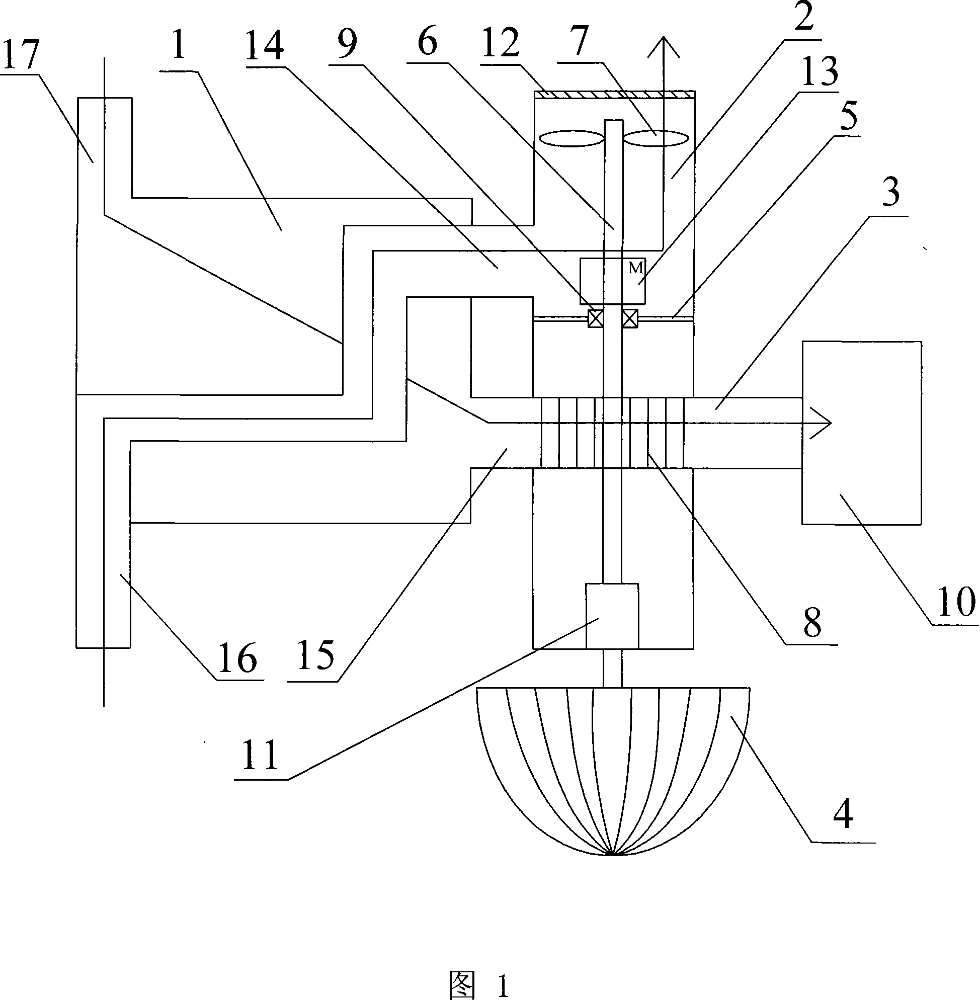
[0007] Specific embodiment 1: Referring to Fig. 1, this embodiment consists of a heat exchanger 1, an air inlet duct 2, an exhaust duct 3, a wind wheel 4, a partition 5, an axle 6, an axial flow impeller 7, and a cross flow impeller 8 Composed of bearing 9, the air outlet of the air inlet duct 2 is connected to the room, the middle part of the air inlet duct 2 is provided with a partition 5, the partition 5 divides the air inlet duct 2 into two spaces, and the exhaust duct 3 is connected with the air inlet The inside of the pipeline 2 passes through vertically, the air outlet of the exhaust duct 3 communicates with the exhaust air shaft 10 of the building, the axle 6 is connected to the divider 5 through the bearing 9 arranged at the center of the divider 5, and the lower end of the axle 6 Passes through the inside of the exhaust duct 3 and is fixedly connected with the wind wheel 4. The cross-flow impeller 8 is sleeved on the part of the wheel shaft 6 located in the exhaust du...

specific Embodiment approach 2

[0008] Specific embodiment 2: Referring to Fig. 1, the difference between this embodiment and specific embodiment 1 is that it adds a detachable coupling 11, and the transmission input end of the detachable coupling 11 is connected with the wind wheel 4, The transmission output end of the detachable coupling 11 is connected with the wheel shaft 6 . When the room does not need ventilation, the detachable coupling 11 can be disconnected, and after the detachable coupling 11 is disconnected, the wheel shaft 6 stops rotating, and the ventilation process stops. Other structures are the same as in the first embodiment.

specific Embodiment approach 3

[0009] Embodiment 3: Referring to FIG. 1 , the difference between this embodiment and Embodiment 1 is that it adds louvers 12 , and the louvers 12 are arranged at the air outlet of the air inlet duct 2 . The louvers 12 can adjust the angle of entry and the amount of air entering the indoor fresh air, and the louvers 12 can be closed when ventilation is not needed. Other structures are the same as in the first embodiment.


PUM


Abstract

It relaters to a sort of the aeration set, the aeration set can reclaim the new wind used the quantity of heat of the nature wind energy to solve the existing problem of the aeration system in that high energy consumption, expensive cost, small new wind quantity, indisposed feel for people. The outlet of the air intake pipe connects with the interior, the middle of the air intake pipe is located the clapboard, the clapboard divide the air intake pipe into the two space, the exhaust duct cross vertically from the air intake pipe, the outlet of the exhaust connects with the air shaft, the wheel axle connects with the clapboard, the one port of the clapboard cross from the exhaust duct and connects with the wheel axle in the method that it can divide or close momentarily, the cross flow wheel axle sheath connects with the wheel axle which is in the part of the exhaust duct, another port of the wheel axle locates in the outlet of the air intake, axial flow wheel axle sheath connects with the wheel axle which is in the one port of the outlet of the air intake pipe, the two port of the heat exchange connects respectively with the air intake pipe and the air outlet pipe. It is characterized in that it can adequately use the wind energy and not consume other energy, and can reclaim the quantity of heat of the indoor air.

Description

technical field [0001] The invention relates to a ventilation device. Background technique [0002] In the cold winter in the north, radiators are generally used for heating indoors. In order to ensure that the indoor heat is dissipated as little as possible, the doors and windows are closed tightly. Due to the lack of air flow, the indoor air quality is relatively poor. General buildings do not have a special ventilation system, and fresh air can only be obtained by opening windows. Due to the effect of thermal pressure, a large amount of cold air will flow into the room after opening the windows, making people feel uncomfortable; for high-rise buildings, due to the outdoor wind Because of the pressure, it is generally not allowed to open windows for ventilation, and a special ventilation system must be installed. This type of ventilation system is often expensive and consumes a lot of energy. In order to save energy and operating costs, general high-rise buildings use sma...

Claims


Application Information

Patent Timeline
Patent Type & Authority Applications(China)
IPC IPC(8): F24F7/007
Inventor 姜益强林文均
Owner HARBIN INST OF TECH
Features
  • R&D
  • Intellectual Property
  • Life Sciences
  • Materials
  • Tech Scout
  • Unparalleled Data Quality
  • Higher Quality Content
  • 60% Fewer Hallucinations
Learn More