
Backlight module and manufacturing method therefor

A technology for a backlight module and a manufacturing method, which are applied in the fields of optics, nonlinear optics, instruments, etc., can solve problems such as development, deficiencies, and unevenness that are unfavorable to the thinning direction of portable flat display devices.

Active Publication Date: 2007-12-05
AU OPTRONICS CORP
View PDF0 Cites 1 Cited by
  • Summary
  • Abstract
  • Description
  • Claims
  • Application Information

AI Technical Summary

Problems solved by technology

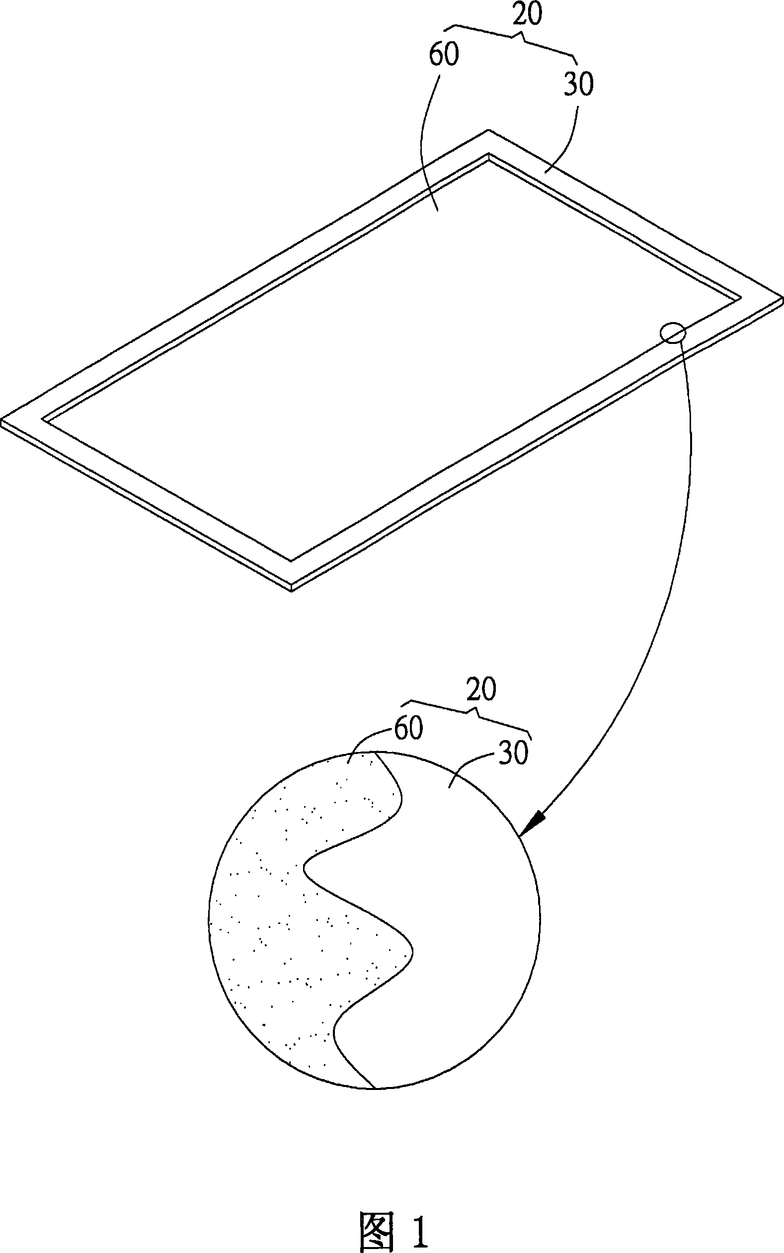
As shown in Figure 1, since the side of the optical plate 60 has no reflective sheet and is uneven, it is easy to form an uneven joint line between the optical plate and the frame when it is combined with the frame body 30, and further reduces the brightness of the panel.
In addition, since the frame body 30 and the optical plate 60 are made of different materials, if the bonding strength is completely controlled by the injection conditions, it will be less stable.
At the same time, under the requirement of thinning, the strength of the double injection of the frame and the optical plate is sometimes slightly insufficient.
All of these are not conducive to the further development of portable flat panel display devices in the direction of thinning

Method used


Image

  • Backlight module and manufacturing method therefor
  • Backlight module and manufacturing method therefor
  • Backlight module and manufacturing method therefor

Examples


Embodiment Construction

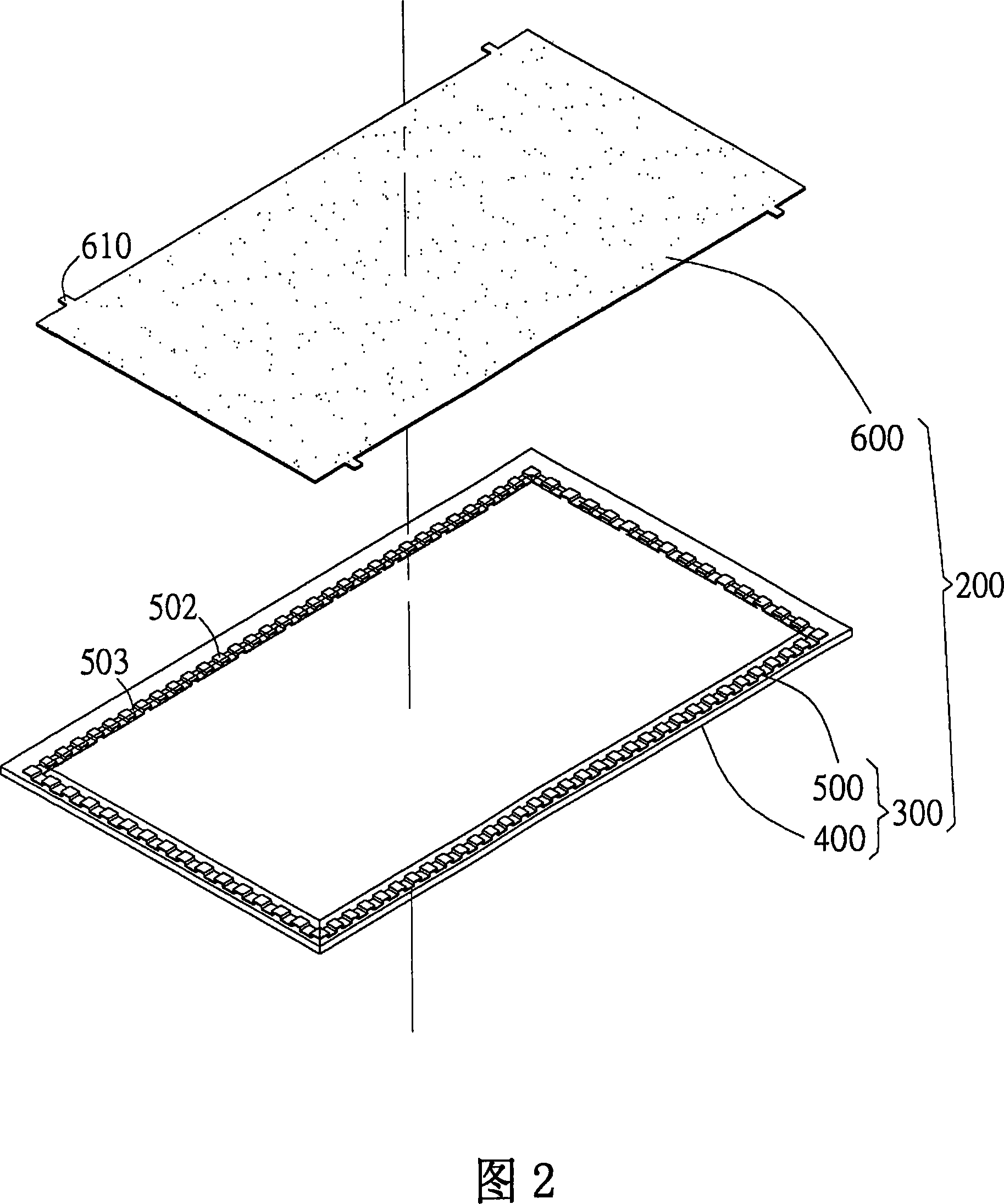
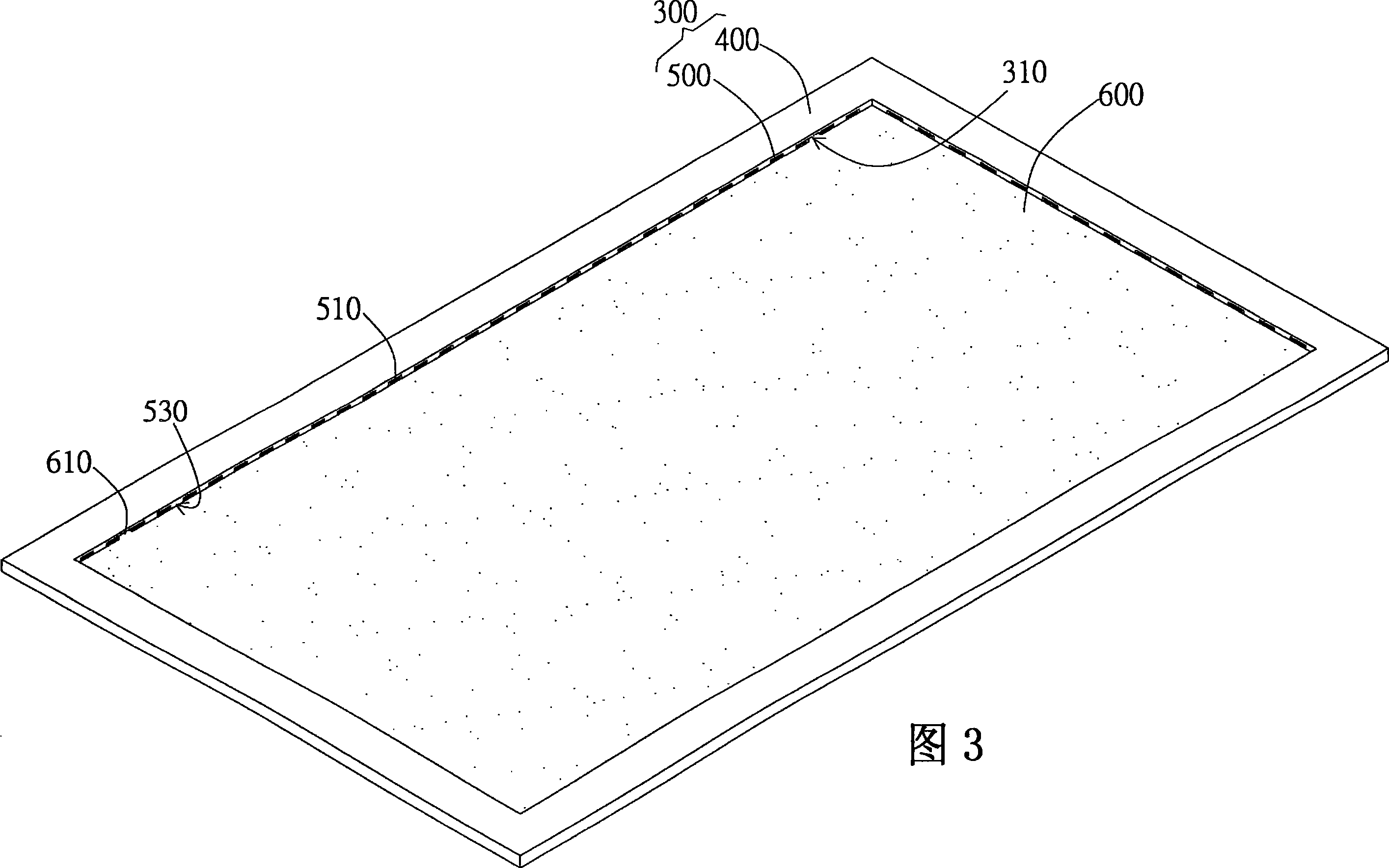
[0039] The present invention provides a backlight module and a manufacturing method thereof. By combining optical plates and at least one material frame to form an integrated structure, the overall strength of the panel is increased and the demand for thinner panel is met. The backlight module of the present invention preferably combines the optical plate, the first material frame, and the second material frame to form an integrated structure by injection technology to increase the overall strength of the panel. In a preferred embodiment, the backlight module of the present invention combines dual-material injection technology to enhance the overall strength of the panel, and connects the plastic frame and the optical plate through a metal frame, such as a light guide plate or other optical plates (such as a diaphragm) Etc. to ensure the maintenance of panel brightness. The backlight module of the present invention is preferably applied to a mobile display device, a portable flat ...


PUM


Abstract

The invention discloses an aphototropism mode and making method, wherein the aphototropism mode consists of frame and optical board, wherein the frame contains first material frame and second material frame; the second material frame is inserted in the first material frame; the strength of the second material is higher than the strength of first material; at least one joint part is formed between the first and second material frames; the optical board is set in the frame with part connecting at least one joint part.

Description

Technical field [0001] The present invention relates to a backlight module and a manufacturing method thereof; specifically, the present invention relates to a backlight module and a manufacturing method thereof that can increase the overall intensity of a panel. Background technique [0002] The advancement of display device technology has met people's various needs in information life, and its application level is very wide, ranging from personal electronic products to computer screens and household appliances. The close integration of display devices and human life can be seen everywhere. With the gradual development of modern electronic digital products toward the design concepts of lightness, thinness and shortness, the design and production of flat display devices are also becoming thinner. [0003] In order to achieve the purpose of lightness and thinness of the current portable flat-panel display device, the dual-material injection technology is generally used to combine ...

Claims


Application Information

Patent Timeline
IPC IPC(8): G02F1/13357G02F1/1333G02F1/1335
Inventor 陈群元徐旭升陈志伟
Owner AU OPTRONICS CORP
Learn More