

Light-emitting element and display device
A technology of light-emitting components and light-emitting devices, which is applied in the direction of electrical components, static indicators, electric solid devices, etc., can solve the problems of low light extraction efficiency and achieve the effect of improving light extraction efficiency
- Summary
- Abstract
- Description
- Claims
- Application Information
AI Technical Summary
Problems solved by technology
Method used
Image

Examples
Embodiment approach 1
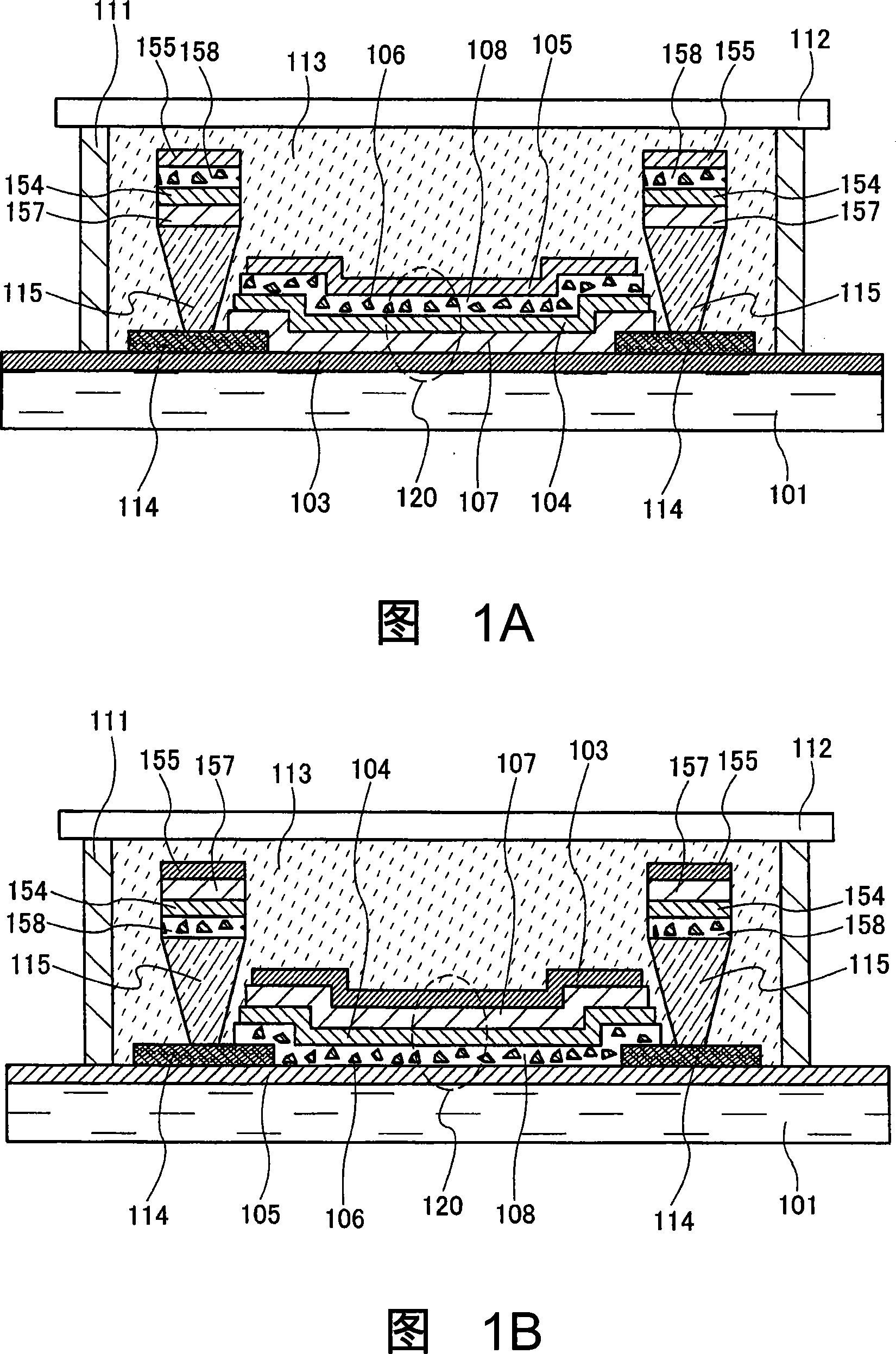
[0043] In this embodiment mode, a form using a thin-film inorganic light-emitting element, which is one of the light-emitting elements of the present invention, is shown. FIG. 1A shows a cross-sectional view of a display device using a top emission structure. In addition, FIG. 1B shows a cross-sectional view of a display device using a bottom emission structure. In addition, in this specification, a top emission structure refers to a structure in which light emission from a light emitting element is extracted from above (the sealing substrate side). On the other hand, the bottom emission structure refers to a structure in which light emission from a light emitting element is extracted from below (the substrate side on which the light emitting element is provided).
[0044] In the following present embodiment, the only difference between FIG. 1A and FIG. 1B is that the positions of the reflective electrode 103 and the light-transmitting electrode 105 and the positions of the f...
Embodiment approach 2
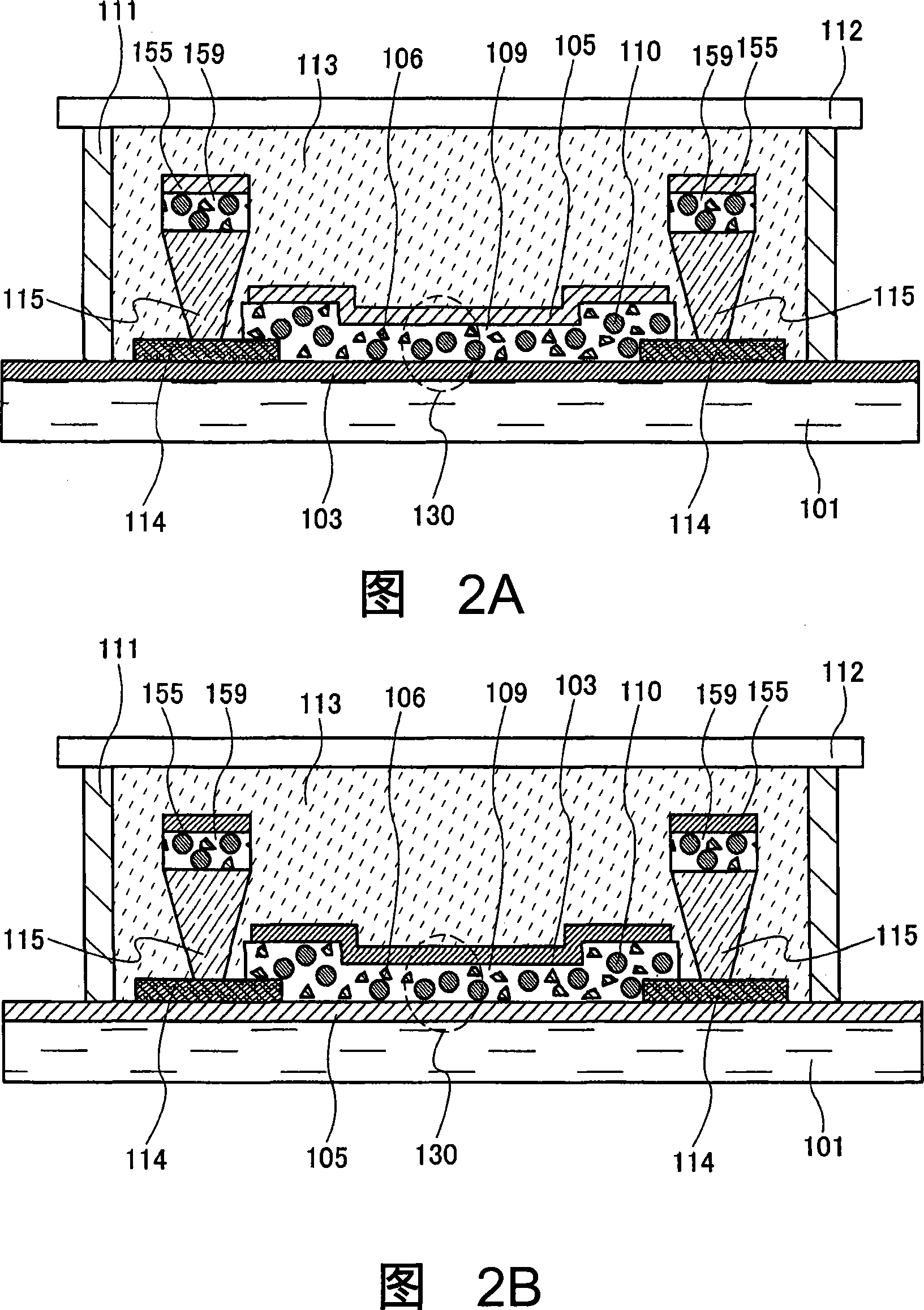
[0087] In this embodiment mode, a mode in which the present invention is applied to a dispersion-type inorganic light-emitting element which is one of light-emitting elements is shown. FIG. 2A shows a cross-sectional view of a display device using a top emission structure. In addition, FIG. 2B shows a cross-sectional view of a display device using a bottom emission structure. The only difference between FIG. 2A and FIG. 2B is that the positions of the reflective electrode 103 and the light-transmissive electrode 105 are reversed, and the formation order of these parts is also reversed. Therefore, unless otherwise specified, description will be made using FIG. 2A of the top emission structure.
[0088] In Embodiment Mode 1, a structure is described in which the light emitting element 120 is formed between the substrate 101 and the substrate 112, and the light emitting element includes the reflective electrode 103, the first dielectric layer 107, the light emitting layer 104, a...
Embodiment approach 3
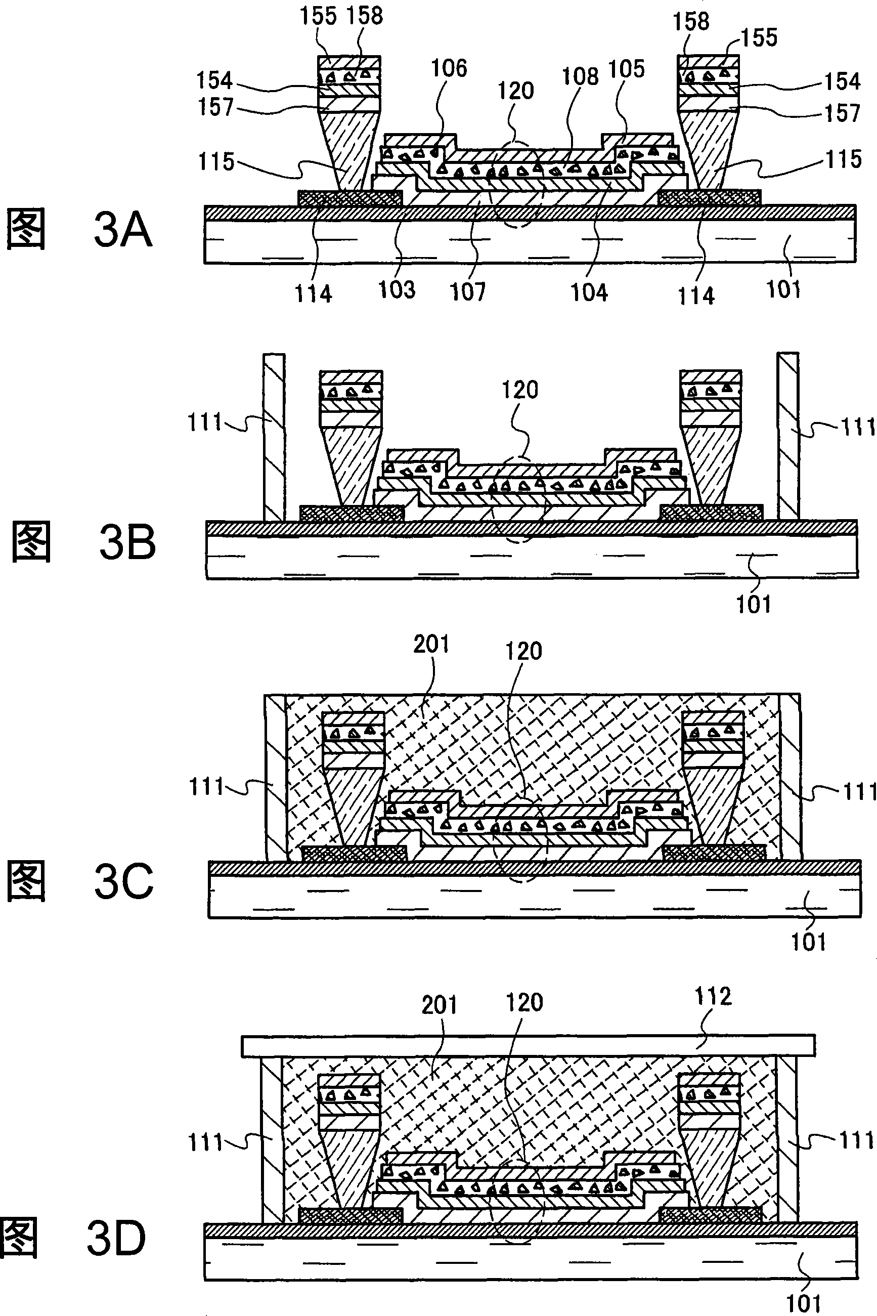
[0101] The present embodiment is described with reference to FIG. 3 . In Embodiment Mode 1, the airtight space between the substrate 101 and the substrate 112 is filled with the gas 113 . However, in the display device of the present embodiment, the space is filled with a solid material prepared by filling a liquid material and curing it. A sealed structure of a display device in which a solid material is disposed between substrates is called a solid sealed structure, and this term is sometimes used to distinguish it from a gas-filled structure. In this specification, the term is also used to distinguish solid-filled structures from gas-filled structures.
[0102] According to the procedure described in Embodiment Mode 1, the substrate 101 up to the formation of the light-transmitting electrode 105 is prepared (FIG. 3A). In addition, insulating layer 114 and partition wall layer 115 covering part of reflective electrode 103 are formed on reflective electrode 103 as in the fi...
PUM
 Abstract
Description
Claims
Application Information