PCB plate double-face drilling and positioning method

A technology of PCB board and positioning method, which is applied in positioning devices, drilling/drilling equipment, components of boring machines/drilling machines, etc., can solve the problems of misalignment of zero points, easy breakage of drill bits, affecting product quality, etc., and achieve positioning accuracy. High, reduce deviation, improve the effect of pass rate

A technology of PCB board and positioning method, which is applied in positioning devices, drilling/drilling equipment, components of boring machines/drilling machines, etc., can solve the problems of misalignment of zero points, easy breakage of drill bits, affecting product quality, etc., and achieve positioning accuracy. High, reduce deviation, improve the effect of pass rate

CN101085472AInactive Publication Date: 2007-12-12SHENNAN CIRCUITS

Image

  • PCB plate double-face drilling and positioning method

Examples


Embodiment Construction

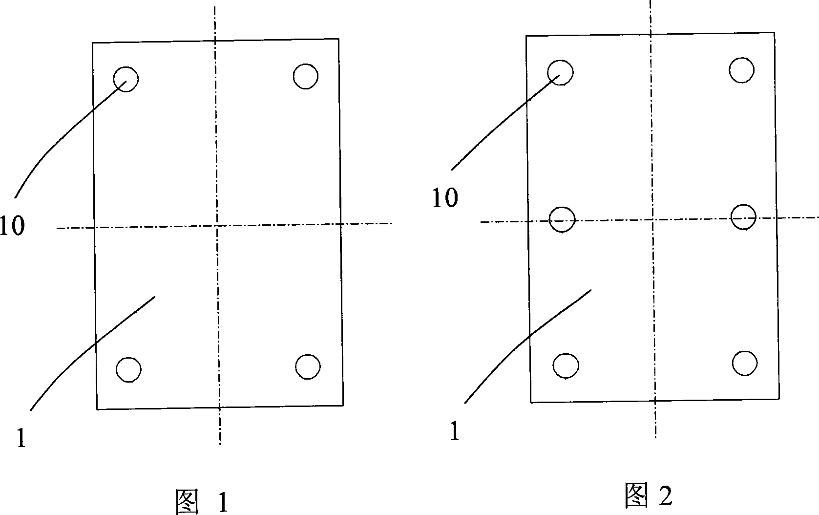
[0009] As shown in Fig. 1, the present invention provides a kind of PCB board double-sided drilling positioning method, it is provided with at least 4 positioning holes 10 on the PCB board 1, and one-to-one correspondence between the drilling jig and the positioning holes Positioning pins are provided, and when holes are drilled from the front and back sides of the PCB board, the positioning pins and the positioning holes are matched one by one to position the PCB board. The positioning holes are distributed symmetrically. According to the size of the PCB board, the number of the positioning holes is generally 4-16, preferably 4-6. In the embodiment shown in FIG. 1 , four positioning holes are arranged symmetrically on the circuit board; while in another embodiment shown in FIG. 2 , six positioning holes are arranged symmetrically on the circuit board.

[0010] The present invention increases the number of positioning holes through the cooperation of positioning holes and pos...


PUM


Abstract

The PCB dual surface drilling positioning has at least four positioning holes on the board, positioning pins on the drilling fixture or drilling platform opposite to the positioning holes, with the positioning pins and the holes matching with each other to fix the PCB board when it drills from either positive or negative side of the board.It can use the interference principle of positioning, reduce the deviation of two positioning zero points, with high positioning precision, and increased in drilling efficiency and yield rate.

Description

technical field [0001] The invention relates to a PCB board drilling method, in particular to a PCB board double-sided drilling positioning method. Background technique [0002] Front and back drilling refers to the process of drilling through holes on both sides of the front and back when the plate is thick and cannot be drilled at one time or the quality of one-time drilling cannot be guaranteed. It is generally used to process small holes with a diameter D≤1.0mm, most of which have a diameter of 0.6-0.8mm. When using this drilling method, when the thickness and diameter of the plate is relatively large, if the same diameter drill is used for drilling on both sides, it is easy to form an "8" hole. In order to solve this problem, a method usually used at present is to increase The diameters of holes drilled on the front and back sides are different, but due to the thickness of the plate, the drill bit is easy to break after increasing to a certain extent, and this problem ...

Claims


Application Information

Patent Timeline
12 Dec 2007
Publication
CN101085472A
IPC
B23B47/00; B23Q3/18
Inventors
武凤伍; 彭勤卫