Manual tool with vibration reduction device

A technology of hand-held machine tool and connecting device, which is applied in the direction of manufacturing tools, striking tools, portable drilling rigs, etc., can solve the problems of large assembly cost and high manufacturing cost, and achieve the effect of preventing locking

Inactive Publication Date: 2007-12-12
HILTI AG
View PDF1 Cites 9 Cited by
  • Summary
  • Abstract
  • Description
  • Claims
  • Application Information

AI Technical Summary

Problems solved by technology

In addition, the rod entails relatively high assembly costs and high manufacturing costs

Method used


Image

  • Manual tool with vibration reduction device
  • Manual tool with vibration reduction device
  • Manual tool with vibration reduction device

Examples


Embodiment Construction

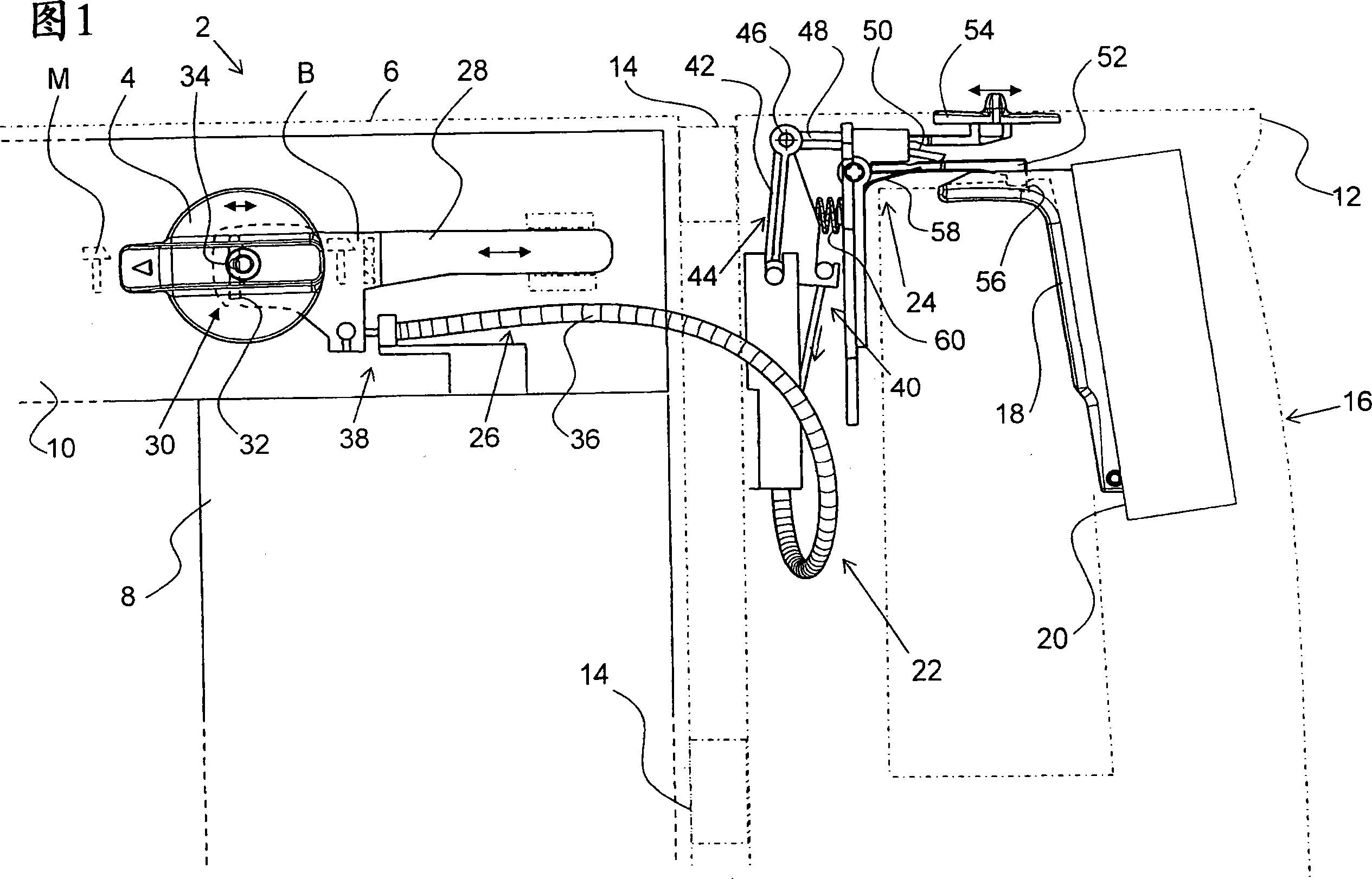
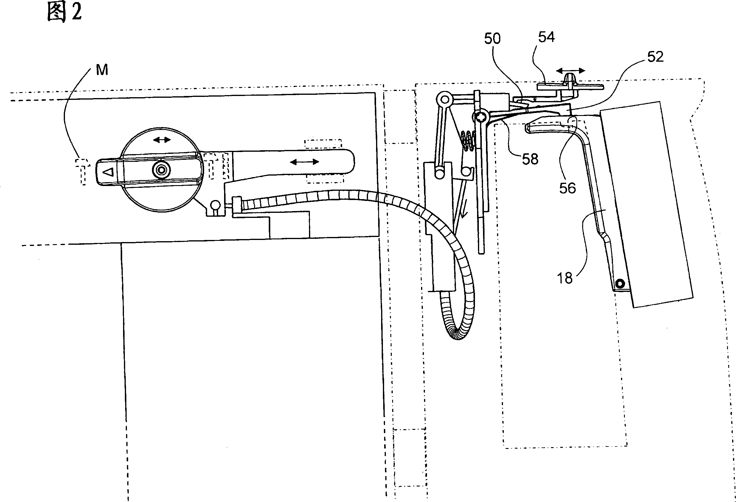
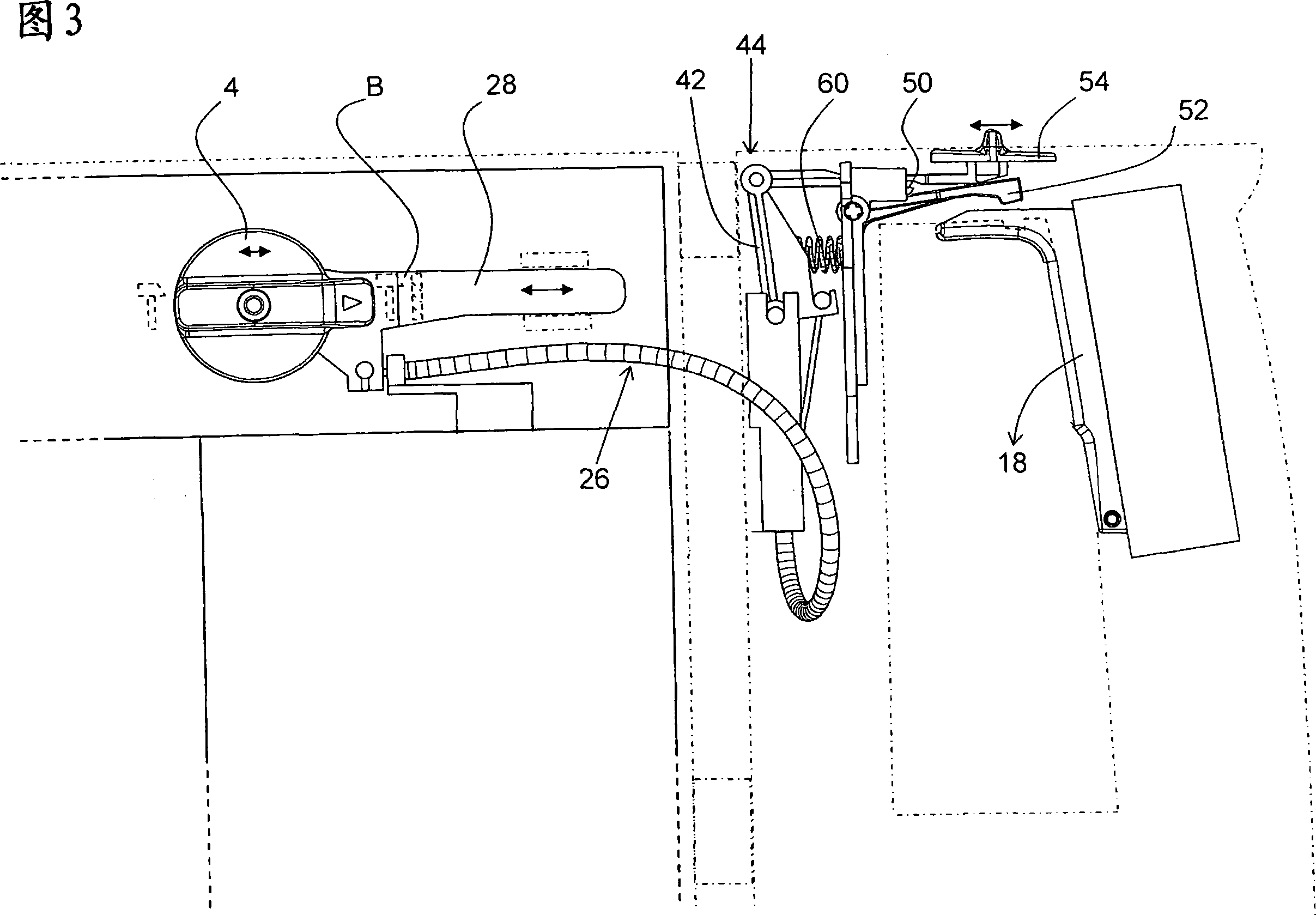
[0018] FIG. 1 partially shows a hand-held power tool 2 in the form of an electrically operated combination hammer. By means of the mode switch 4, the hand-held power tool can be switched between a chisel function with pure percussion operation and a drilling function, as indicated by a chisel position M and a drilling position B for the hammer percussion drilling or simple drilling.

[0019] The hand-held power tool 2 has a main housing 6 in which a motor unit 8 and a transmission unit 10 are accommodated. A further handle housing 12 is held on the main housing 6 with an intermediate layer of a damping device 14 having, for example, a spring mechanism not described in detail. The handle housing 12 forms a handle 16 which can be grasped by hand, and at the same time the switching pawl 18 of the motor switch 20 can be actuated by hand in order to actuate the motor unit 8 or the hand-held power tool 2 as a whole.

[0020] During operation, vibrations are generated at the main h...


PUM


Abstract

A hand-held machine tool (2) has a main housing (6) at which vibrations are generated during operation, a handle housing (12) that is held at the main housing (6) with the intermediary of a vibration-reducing device (14), and an adjusting arrangement (22) which has an adjusting device on the main housing side which can be adjusted between at least two positions and an adjusting device on the handle housing side which can be adjusted between at least two positions and which is mechanically connected to the adjusting device (26) on the main housing side by an adjusting connection (26). The adjusting connection (26) has a flexible vibration-reducing portion (36) between the handle housing (12) and the main housing (6).

Description

technical field [0001] The invention relates to a hand-held power tool, in particular in the form of an electric combination hammer that can be used optionally as a drill hammer or chisel hammer, comprising a main housing on which vibrations are generated during operation. In addition, the hand-held power tool has a handle housing, which is held on the main housing with an intermediate damping device, which dampens the vibrations that occur or the handle housing is substantially connected to the main housing. Body-generated vibration isolation. In addition, the adjustment device is provided with an adjustment mechanism on the side of the main housing adjustable between at least two positions and an adjustment mechanism on the side of the handle housing adjustable between at least two positions. The adjustment mechanism on the body side is mechanically coupled to the adjustment mechanism on the main housing side via an adjustment connection. Background technique [0002] In...

Claims


Application Information

Patent Timeline
Patent Type & Authority Applications(China)
IPC IPC(8): B25F5/02B25D17/04B25D16/00B23B45/16H01H9/06
CPCB25D17/043B25D16/006B25D2216/0015B25D2216/0023B25D2250/261
Inventor F·克里斯滕R·莫伊尔R·舒尔茨
Owner HILTI AG
Why Eureka
Try Eureka