Warp knitting machine

A warp knitting machine and machine body technology, applied in the field of warp knitting machines, can solve problems such as increasing repairs

Active Publication Date: 2007-12-12
KARL MAYER STOLL R&D GMBH
View PDF0 Cites 2 Cited by
  • Summary
  • Abstract
  • Description
  • Claims
  • Application Information

AI Technical Summary

Problems solved by technology

This in turn requires additional repairs

Method used


Image

  • Warp knitting machine
  • Warp knitting machine

Examples


Embodiment Construction

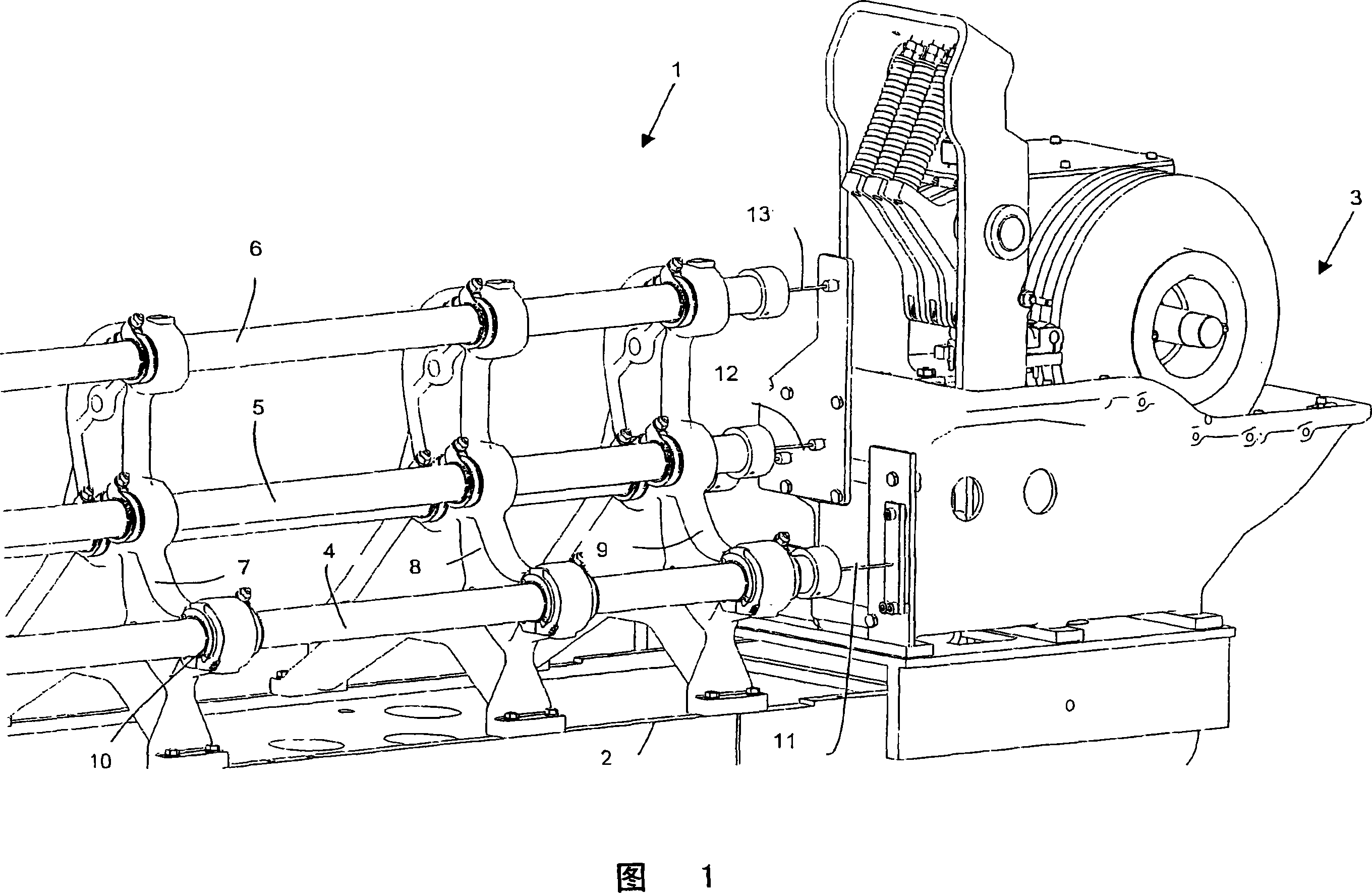
[0025] FIG. 1 shows a partial view of a warp knitting machine 1 having a body 2 . At an axial end of the warp knitting machine 1, a jacquard drive or jacquard device 3 is provided, which makes the not shown knitting tool bar, such as the bar, move back and forth according to the desired pattern of a knitted fabric. .

[0026] The warp knitting machine has a plurality of bearing shafts 4, 5, 6, which are supported in wall panels 7, 8, 9, which are connected to the machine body 2, for example by means of screws. The support shafts 4, 5, 6 are supported in the wall plates 7, 8, 9 by means of bearings 10 which allow the rotational movement of the support shafts 4, 5, 6, but not the support shafts 4, 5, 6 in their axial direction towards Wall panels 7, 8, 9 support.

[0027] The above-mentioned, not shown, comb bars are connected to the support shafts 4, 5, 6 via looping tool bars. If the bearing shafts 4, 5, and 6 are rotated, the corresponding knitting tool bars are swung. Th...


PUM


Abstract

The invention relates to a warp knitting machine (1) having a body (2) and at least one axially extending bearing shaft (4, 5, 6) for a knitting tool shaft, which are rotatably supported And is fixed in the axial direction relative to a fixedly positioned machine component (3) to the machine body (2). It is desirable to facilitate the axial fixation of the support shaft. Provision is made for this to connect the bearing shafts (4, 5, 6) to the machine component (3) in the axial direction via a torsion link (11, 12, 13).

Description

technical field [0001] The invention relates to a warp knitting machine having a body and at least one axially extending support shaft for a knitting tool rod, which is rotatably supported and fixedly positioned relative to the body in the axial direction The machine components are fixed. Background technique [0002] In order to produce knitwear in a warp knitting machine, the loop forming tools must be moved relative to each other in order to form the loops. Such a movement should be described in terms of comb needles (legenadel). Similar kinematic components are however also present in other loop forming tools. [0003] During knitting, the bar needles must be swiveled both through the needle gaps between the knitting needles, and must also be perpendicular to this movement, ie parallel to a row in which the knitting needles are arranged. The final movement parallel to the bearing shaft is brought about by a jacquard drive or a jacquard drive. The first movement is pr...

Claims


Application Information

Patent Timeline
Patent Type & Authority Applications(China)
IPC IPC(8): D04B27/00
CPCD04B27/26
Inventor R・肯珀K・布兰德尔H・利布H・克莱尔
Owner KARL MAYER STOLL R&D GMBH
Why Eureka
Try Eureka