Electric slip

A technology of electric slips and slips, which is applied to drilling equipment, instruments, display devices, etc., can solve the problems of numerous pipelines on site, and achieve the effect of improving safety

Pending Publication Date: 2021-06-18
JIANGSU RUTONG PETRO MASCH CO LTD
View PDF0 Cites 1 Cited by
  • Summary
  • Abstract
  • Description
  • Claims
  • Application Information

AI Technical Summary

Problems solved by technology

[0004] The purpose of the present invention is to provide an electric slip driven by the slip body through four cylinders, which solves the problem of numerous on-site pipelines that must exist in the pneumatic or hydraulic control mode. , to avoid the accidental loss of the tooth plate that may be caused by misoperation, and it is easier to replace the tooth plate carrier directly with the help of the logo

Method used


Image

  • Electric slip
  • Electric slip
  • Electric slip

Examples


Embodiment approach

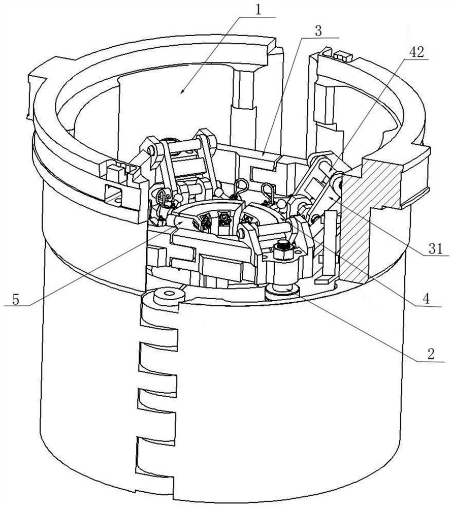
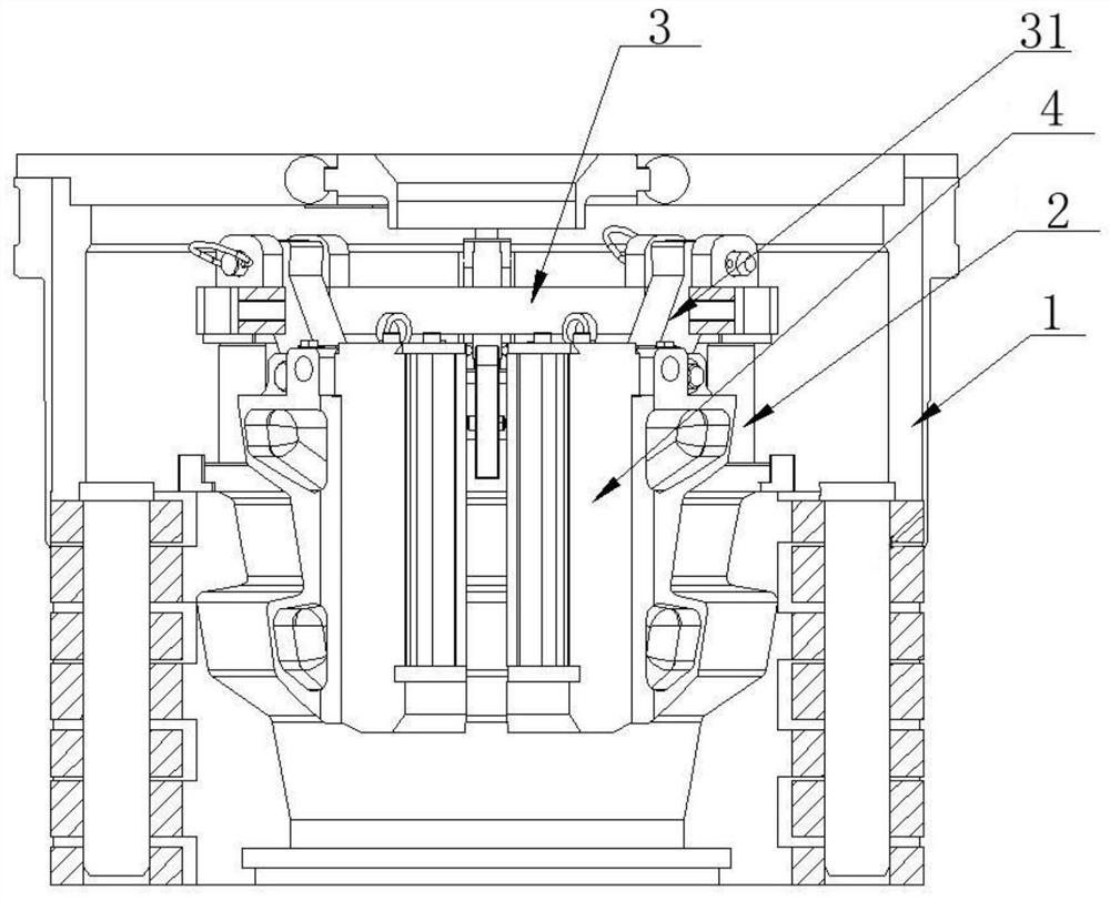
[0040] Driven by the lifting electric cylinder 2, the balance beam 3 rises, and at this time, the safety electric cylinder 63 in the safety mechanism is in a power-off state, and the piston rod end of the safety electric cylinder 63 is retracted, driving the safety lever 62 to lean towards the balance beam 3 side, and close to the side end of the balance beam 3, without hindering the rise of the balance beam 3, as the balance beam 3 continues to rise, the support of the balance beam 3 is lost, and the safety lever 62 is further inclined to the balance beam 3 below;

[0041] When the slip body 4 rises to the sensing position of the ascending travel switch, the lifting electric cylinder 2 acts to stop continuing to rise and keep the slip body 4 at the current position. After the balance beam 3 goes down to the safety lever 62, it is resisted by the safety lever 62, so as to avoid the situation of stuck drilling caused by the continued decline, which plays a role of mechanical in...


PUM


Abstract

The invention provides an electric slip. The electric slip comprises a main body, a lifting electric cylinder, a balance beam, a slip body, a tooth plate carrier and a safety mechanism, wherein the lifting electric cylinder and the safety mechanism are arranged in the main body; the piston rod end of the lifting electric cylinder is connected with the balance beam; the balance beam is connected with the slip body through a connecting rod; the tooth plate carrier is detachably arranged on the slip body; the safety mechanism comprises a safety base, a safety lever and a safety electric cylinder; the safety base is fixedly arranged on the main body; the safety lever is rotatably arranged on the safety base; and the safety electric cylinder is arranged at one end of the safety lever. The electric slip solves the problem that various field pipelines are inevitably available by adopting a pneumatic or hydraulic control mode; and through locking arrangement on the slip body and the tooth plate carrier, the condition that a tooth plate is accidentally dropped possibly caused by misoperation is avoided, and the tooth plate carrier can be replaced more simply and conveniently by directly using an identifier.

Description

technical field [0001] The invention relates to the field of oil drilling equipment, in particular to an electric slip. Background technique [0002] In the prior art, the drilling slips are controlled and driven by pneumatic or hydraulic pressure, and there are many external pipelines on site, which lacks safety. During the actual drilling process, sometimes the slips need to be pulled out according to the on-site process requirements, and it is very inconvenient to disassemble the pipeline, and it is easy to be confused if the labels are not clear during disassembly and assembly. At the same time, when the specification of the drilling tool needs to be changed on site, the slip body or the die plate needs to be replaced. The specification of the slip body or the die plate is completely selected based on experience. It is easy to have a mismatch of specifications, which brings inconvenience to the assembly and has a great impact on On-site efficiency. [0003] Therefore, ...

Claims


Application Information

Patent Timeline
Patent Type & Authority Applications(China)
IPC IPC(8): E21B19/10G09F7/00
CPCE21B19/10G09F7/00
Inventor 张建许波兵何云华顾雪亮缪鑫
Owner JIANGSU RUTONG PETRO MASCH CO LTD
Why Eureka
Try Eureka