Forklift motor stator processing tool and operation method thereof

A motor stator and forklift technology, which is applied in the field of forklift motor stator processing tooling, can solve the problems of complexity, many processes, and the inability to guarantee the roundness and concentricity of the motor stator core, so as to achieve fewer processing steps, improve coaxiality, and structure simple effect

Active Publication Date: 2019-04-16
ZHEJIANG JINLONG ELECTRICAL MASCH CO LTD
View PDF1 Cites 1 Cited by
  • Summary
  • Abstract
  • Description
  • Claims
  • Application Information

AI Technical Summary

Problems solved by technology

[0003] At present, the production method of the stator core is to put the wound sub-core on the mold core, and then tighten the sub-core through the tightening ring, manually adjust the tightening force, and measure the outer circle with a vernier caliper, as far as possible. The outer diameter is within the appropriate range, and then put it on the laser welding equipment for welding, because there are some joints in the axial direction of the iron core with tight hoops that cannot be welded, and the iron core must be reshaped after welding. The roundness of the motor should be adjusted well. This method is complex and requires many procedures, and it cannot guarantee the roundness and concentricity of the stator core of the motor.

Method used


Image

  • Forklift motor stator processing tool and operation method thereof
  • Forklift motor stator processing tool and operation method thereof
  • Forklift motor stator processing tool and operation method thereof

Examples


specific Embodiment approach

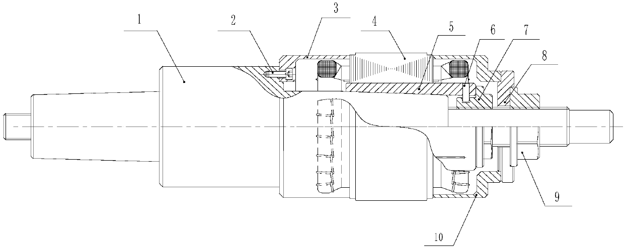
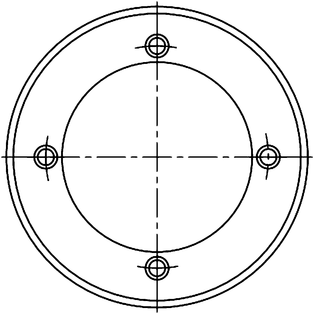
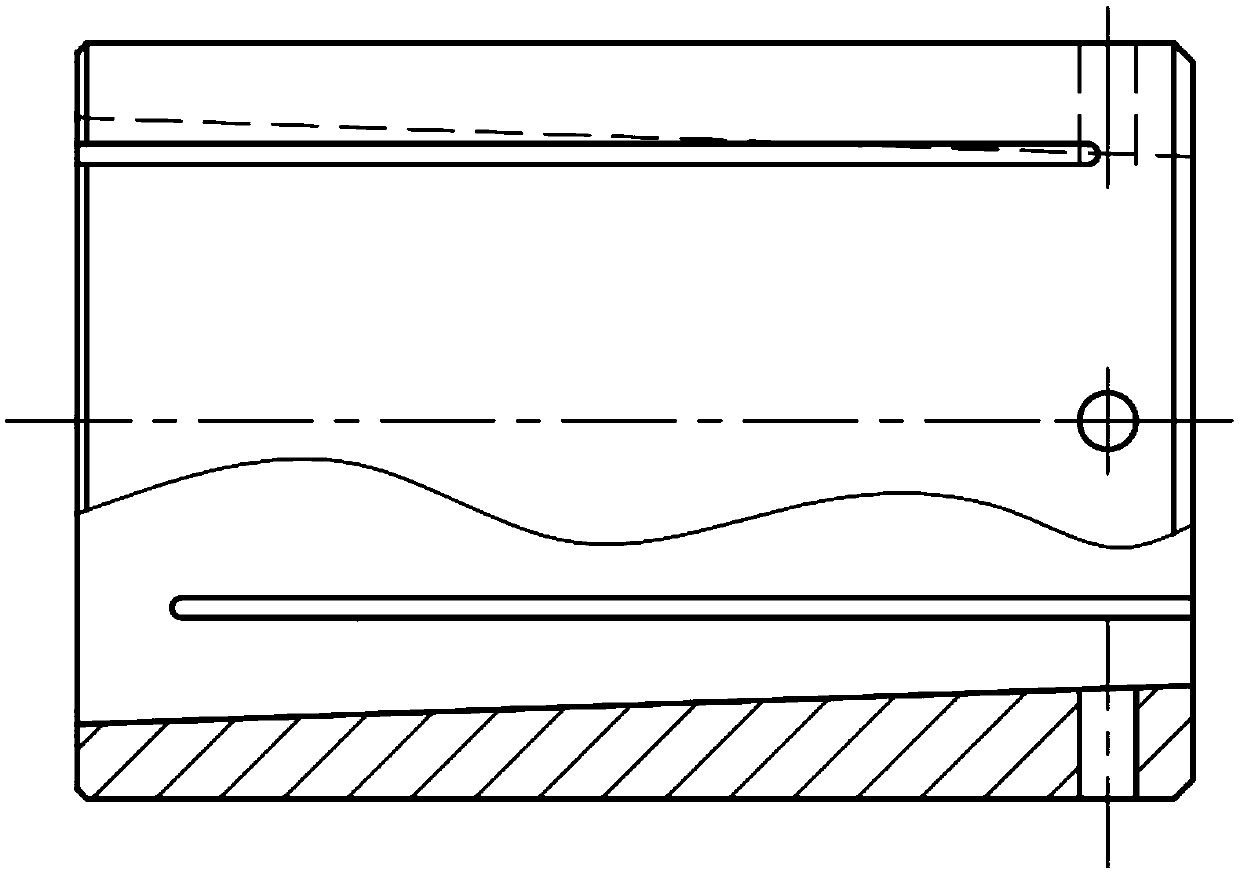
[0030] Figure 1 to Figure 8 It shows a specific embodiment of the present invention, a forklift motor stator processing tool and its operation method, including a mandrel 1, a hexagon socket head cap screw 2, a mold doubler plate 3, a winding stator core 4, an expansion sleeve 5, Cylindrical pin 6, left lock nut 7, mold backing plate 8, right lock nut 9 and mold pressure plate 10, the mold doubler plate 3 is a cylindrical structure and the mold doubler plate 3 passes through the inner hexagon The cylindrical head screw 2 is fixedly installed on the cylindrical positioning boss on the mandrel 1, the stator core 4 with winding is installed on the expansion sleeve 5 and the left end surface of the stator core 4 with winding is pushed against the right end surface of the mold doubler plate 3 , the expansion sleeve 5 is made of 40Cr material and the center of the expansion sleeve 5 is provided with a conical hole. There are two groups of rectangular strip cutting grooves evenly d...


PUM


Abstract

The invention discloses a forklift motor stator processing tool and an operation method thereof. The main content is that a mould cover plate is fixedly mounted on a cylindrical positioning boss on amandrel by a hexagon socket head screw; a winding stator core is mounted on a tensioning sleeve and a left end face of the winding stator core is placed on a right end surface of the mould cover plate, the tensioning sleeve is mounted on a conical section of the mandrel, a left locking nut is mounted on a threaded section of the mandrel and the left locking nut is placed on the right end face of the tensioning sleeve, the cylindrical pin is installed in a radial mounting hole formed in the riser sleeve, and the tail end of the cylindrical pin is clamped in the annular clamping slot formed in the left locking nut, and a mould press plate is mounted on the cylindrical positioning boss on the mould backing plate, the right locking nut is mounted on the threaded section of the mandrel and theleft locking end of the right locking nut is placed on the bottom surface of the annular groove on the mould backing plate. The forklift motor stator processing tool has a simple structure, is low incost, is simple to install, and the processing precision and work efficiency can be improved.

Description

technical field [0001] The invention relates to the technical field of motor stator processing tooling, in particular to a forklift motor stator processing tooling and an operating method thereof. Background technique [0002] The motor is composed of stator, rotor, end cover, casing, etc., and the stator is composed of stator core, skeleton, winding and terminal board, etc. The stator core is composed of many pieces of iron core. First, the sub-iron core is covered with the skeleton and the winding is wound, and then the sub-iron core wound with the wire is assembled into a stator core, then the stator is put into the casing, and finally the rotor end cover is assembled to form a complete motor. The sub-iron core Assembling the stator core requires laser welding at the joints of the stator core to form a whole stator core. The key performance of the motor (such as vibration, temperature rise, noise, etc.) has a great influence on the concentricity of the inner and outer dia...

Claims


Application Information

Patent Timeline
Patent Type & Authority Applications(China)
IPC IPC(8): H02K15/02
Inventor 叶叶吴小夫
Owner ZHEJIANG JINLONG ELECTRICAL MASCH CO LTD
Why Eureka
Try Eureka