Active type fume exhauster

A range hood, active technology, applied in the direction of oil fume removal, heating method, household heating, etc., can solve the problems of large power consumption, inconvenient operation, difficult to completely eliminate the oil fume, etc., to achieve convenient collection of waste oil and reduce heat Baking, cooking environment bright effect

Inactive Publication Date: 2007-12-12
张清乐 +1
View PDF0 Cites 7 Cited by
  • Summary
  • Abstract
  • Description
  • Claims
  • Application Information

AI Technical Summary

Problems solved by technology

[0003] 1. The effect of oil fume removal is not ideal, and it is difficult to completely remove the oil fume, especially with the improvement of people's living standards, the amount of oil fume has increased greatly. The current solution is to increase the power of the exhaust fan, but it needs to consume a lot of electric energy, and the effect is not good. not obvious
[0004] 2. It is difficult to collect waste oil
The volume of the oil collection cup of the existing range hood is very small, and the waste oil must be cleaned frequently after it is full, which is very inconvenient to operate; moreover, the waste oil in the oil collection cup is easy to overflow and splash into the food during the cooking process , affecting the taste of food and human health
[0005] 3. It is inconvenient to clean the range hood
Because the existing exhaust (suction) range hoods have various defects such as unsatisfactory oil discharge effect, there is a great demand for cleaner and more convenient range hoods

Method used


Image

  • Active type fume exhauster
  • Active type fume exhauster

Examples


Embodiment 1

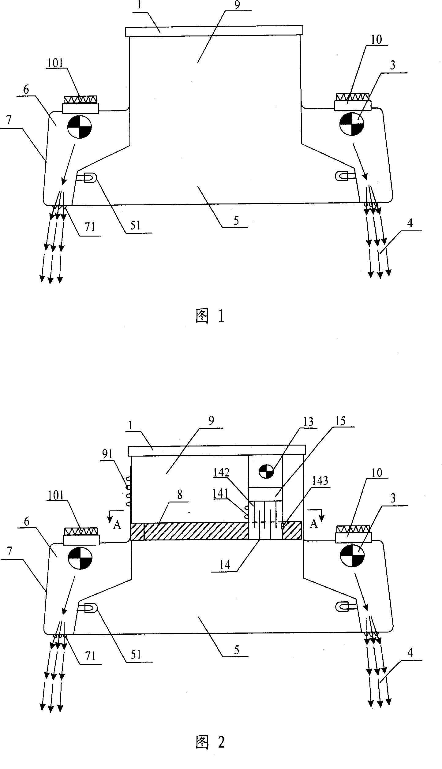
[0026] As shown in Figure 1, it includes a box body 7, the bottom of the box body 7 is recessed with a smoke collection chamber 5, a hollow cavity 6 is formed between the outer casing of the box body 7 and the smoke collection chamber 5, and the left and right sides of the hollow cavity 6 are respectively provided with The air supply inlet 10, the air supply inlet 10 is respectively equipped with a blower fan 3 and a fresh air filter device 101, the hollow cavity 6 is located around the bottom of the box body 7 and is provided with an air supply outlet 71 that can form a wind wall 4, and the smoke collection cavity 5 An air exhaust port 1 is opened on the top, which passes through the box body 7 and extends to the outside of the box body 7 , and an air exhaust duct 9 is formed between the air exhaust port 1 and the top of the smoke collecting chamber 5 .

[0027] In the running state, the blower 3 sends the fresh air into the hollow cavity 6 from the air supply inlet 10 after b...

Embodiment 2

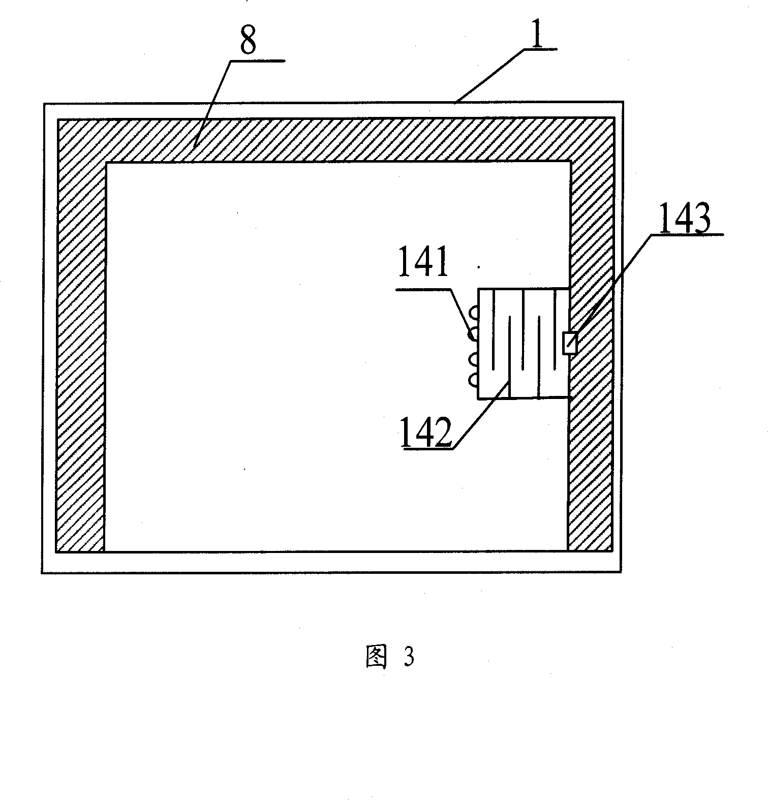
[0034] As shown in Figures 2 and 3, in order to further improve the smoke exhaust effect and solve the problem of waste oil collection, this embodiment is based on Embodiment 1, and an exhaust fan 13 is arranged in the exhaust duct 9, and the bottom of the exhaust fan 13 is arranged There is a fume separator 14 and a plenum 15 , and the fume separator 14 communicates with the exhaust fan 13 through the plenum 15 . The bottom edge of the exhaust duct 9 is provided with a waste oil collection tank 8, which is in close contact with one side of the oil fume separator 14. The side of the oil fume separator 14 is provided with oil fume inlet holes 141, and the inside is interlaced with oil fume separation plates 142. An oil discharge port 143 is opened at the contact of the oil collection tank 8 .

[0035] As described in Embodiment 1, the oil fume is driven out of the exhaust outlet 1 by the air pressure difference formed by the wind wall 4 . 141 enters the oil fume separator 14 a...


PUM


Abstract

The invention involves a active smoke exhaust ventilator, its cavity is opened with air feeding inlet and also is equipped with air feeder, the cavity is located on the periphery of said box body which bottom is opened with the air feeding outlet forming wind wall, the top is also equipped with air discharging mouth which passes through said box body and extends out said box body. In the operation condition, the air feeder brings new air into hollow cavity and discharges air out the box body from air feeding outlet to form wind wall, the air pressure difference is formed under the function of wind wall and drives oil smoke discharge from air discharging mouth actively. It also is combined with air discharging device and oil smoke separating device, so the oil smoke elimination is more exhaustive, the waste oil collection and the cleaning of smoke exhaust ventilator are more convenient.

Description

technical field [0001] The invention relates to a range hood, in particular to a range hood equipped with a blower, which generates an air wall to form an internal and external air pressure difference, and uses an independent closed air supply and exhaust system to actively discharge the range hood outside. Background technique [0002] The operating principle of existing exhaust (suction) range hood is: the body is provided with exhaust blower, and exhaust blower produces strong suction when working, drives oil fume to flow, and it is discharged outdoor rapidly. The waste oil condensed during the smoke exhaust process flows into the oil collection tank along the inner wall of the range hood box, and then flows into the oil collection cup from the opening of the oil collection tank. When the oil is full, the oil collection cup is cleaned. The shortcoming of existing range hood (suction) is: [0003] 1. The effect of oil fume removal is not ideal, and it is difficult to comp...

Claims


Application Information

Patent Timeline
Patent Type & Authority Applications(China)
IPC IPC(8): F24C15/20
Inventor 张清乐柴玉生
Owner 张清乐
Why Eureka
Try Eureka