Light conducting board

A light guide plate and light guide layer technology, which is applied in the field of light guide plates, can solve problems such as high cost and complicated assembly, and achieve the effect of reducing costs and omitting reflective sheets

Active Publication Date: 2007-12-12
AU OPTRONICS CORP
View PDF0 Cites 25 Cited by
  • Summary
  • Abstract
  • Description
  • Claims
  • Application Information

AI Technical Summary

Problems solved by technology

However, the structure of this kind of backlight module is relatively complicated in assembly, and it is necessary to cooperate with the reflective sheet A40 to reflect the light out.
Therefore, the assembly components of the backlight module must have the reflective sheet A40, thus causing the high cost of the backlight module.

Method used


Image

  • Light conducting board
  • Light conducting board
  • Light conducting board

Examples


Embodiment Construction

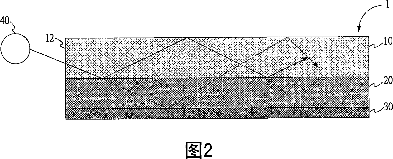
[0027] FIG. 2 is a schematic diagram of the first embodiment of the light guide plate of the present invention. The light guide plate 1 proposed by the present invention is used to transmit incident light 40 , and the light guide plate 1 includes: a first light guide layer 10 , a second light guide layer 20 , and a surface layer 30 .

[0028] The first light guiding layer 10 has an end surface 12 through which incident light 40 enters the first light guiding layer 10 . The second light guiding layer 20 is formed under the first light guiding layer 10 , and the refractive index of the second light guiding layer 20 is smaller than that of the first light guiding layer 10 . As shown in FIG. 2 , when the incident light 40 enters from the end surface 12 of the first light guiding layer 10 and reaches the interface between the first light guiding layer 10 and the second light guiding layer 20, most of the incident light 40 will Due to total reflection, it is conducted in the first ...


PUM


Abstract

A light conducting plate comprises the first and second optical layer, surface layer, the second light conducting layer formed under the first light conducting layer, with the second layer deflection rate less than the first light conducting deflection rate, and the surface layer formed at the lower surface of the secondary optical layer. It can save reflective plate to reduce overall cost and conforming to thin and light demand.

Description

technical field [0001] The invention relates to a light guide plate, in particular to a light guide plate in a backlight module. Background technique [0002] Among displays, a liquid crystal display (LCD) has more advantages than a cathode ray tube (Cathode Ray Tube, CRT) display. Therefore, the current display market has gradually moved towards the trend of LCD replacing CRT displays. The lightness and thinness of LCD is an important one among its many advantages. [0003] The backlight module is one of the important components in the LCD. FIG. 1 shows the architecture of a conventional backlight module. The figure shows the structure of a traditional side-entry backlight module, which is assembled from the following components: diffuser sheet A10, reverse prism sheet A20, light guide plate A30, reflector sheet A40, frame A50, lamp unit A60, bracket A70 , screw A80, and grounding component A90, etc. Under the structure of the backlight module, a reflective sheet A40 i...

Claims


Application Information

Patent Timeline
Patent Type & Authority Applications(China)
IPC IPC(8): G02B6/00G02B1/04G02F1/13357B32B33/00G02F1/1335
Inventor 邓雅薇萧淳中
Owner AU OPTRONICS CORP
Why Eureka
Try Eureka