Magnetic resonance device and method

A device, inspection area technology, applied in the field of computer programs, which can solve problems such as poor image quality, distortion, etc.

Inactive Publication Date: 2007-12-12
KONINKLIJKE PHILIPS ELECTRONICS NV
View PDF1 Cites 13 Cited by
  • Summary
  • Abstract
  • Description
  • Claims
  • Application Information

AI Technical Summary

Problems solved by technology

This in turn will have a very bad distortion effect on the image quality
As a result, the known system requires a bulky battery for energy storage in order to ensure adequate power supply during the MR signal acquisition period, when the inductive feed must remain switched off

Method used


Image

  • Magnetic resonance device and method
  • Magnetic resonance device and method

Examples


Embodiment Construction

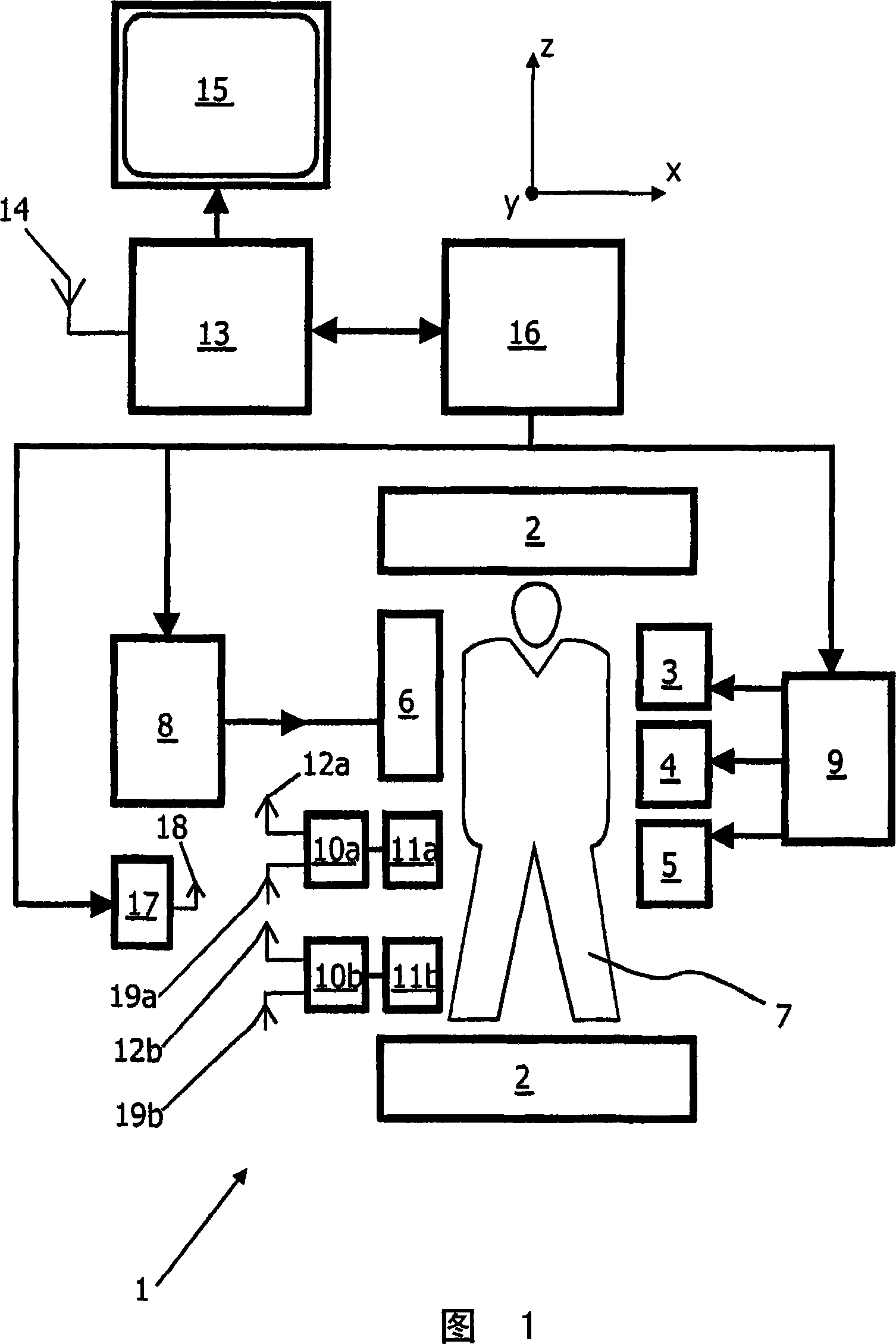
[0021] A magnetic resonance imaging system 1 according to the invention is shown in block diagram form in FIG. 1 . The device 1 includes a group of main magnetic coils 2 and three groups of gradient coils 3, 4 and 5, the group of main magnetic coils is used to generate a static and uniform main magnetic field, each group of gradient coils is used to superimpose an additional magnetic field, the additional The magnetic field has a controllable strength and has a gradient in a chosen direction. Traditionally, the direction of the main magnetic field is labeled z-direction, and the two directions perpendicular to it are labeled x-direction and y-direction. The gradient coils are powered by a power supply 9 . The device 1 also includes a radiation transmitter 6, an antenna or coil, for transmitting radio frequency (RF) pulses to a body 7 placed in the examination region of said device 1, the radiation transmitter 6 being coupled to a modulator 8 for used to generate and modulate...


PUM


Abstract

The invention relates to a device (1) for magnetic resonance imaging of a body (7), comprising a main magnet (2) for generation of a stationary and substantially homogeneous main magnetic field within the examination zone, a plurality of wireless receiving units (10a, 10b) placed in or near the examination zone, and sampling means (21a, 21b) operating at a variable sampling frequency for sampling the received MR signals and for converting them into digital signal samples. In order to provide an MR device (1), which is arranged to inductively energize the wireless receiving units (10a, 10b) without interference with the nuclear spin system of the examined object (7) and which does not necessarily require bulky energy storage means for the operation of the wireless receiving units (10a, 10b), the invention proposes to make provision for energizing means (17) generating an RF energizing field within the examination zone for inductively supplying electric power to the wireless receiving units (10a, 10b), wherein the frequency of the RF energizing field is an integer multiple of the sampling frequency.

Description

technical field [0001] The invention relates to an apparatus for magnetic resonance (MR) imaging. [0002] Furthermore, the invention relates to a method for MR imaging and also to a computer program for an MR imaging device. Background technique [0003] In MR imaging, an object (usually the patient's body) is placed in a stationary and substantially uniform main magnetic field (B 0 ), by switching the RF field (B 1 ) and magnetic field gradient pulses are applied to the subject to generate phase-encoded magnetic resonance signals which are subsequently scanned to obtain information from the subject and reconstruct images thereof. Since the initial development of MRI, the number of clinically relevant fields in which MRI is applied has grown enormously. MRI can be applied to almost every part of the body, and MRI can be used to obtain information about several important functions of the human body. The pulse sequence applied during the MR scan fully determines the chara...

Claims


Application Information

Patent Timeline
Patent Type & Authority Applications(China)
IPC IPC(8): G01R33/36G01R33/3415
CPCG01R33/3692G01R33/3415G01R33/3621
Inventor M·J·A·M·范赫尔沃特J·P·格罗恩R·P·克莱霍斯特C·L·G·哈姆
Owner KONINKLIJKE PHILIPS ELECTRONICS NV
Why Eureka
Try Eureka