Probe holder system, message for fixing a probe holder system and method for adjusting a probe

A technology of fixed parts and fixed distances, which is applied in the direction of measuring devices, instruments, measuring instrument components, etc., and can solve problems such as the limitation of adjustment range

Inactive Publication Date: 2007-12-19
SIEMENS AG
View PDF0 Cites 12 Cited by
  • Summary
  • Abstract
  • Description
  • Claims
  • Application Information

AI Technical Summary

Problems solved by technology

Another disadvantage of the described device is that its adjustment range is limited by the length of the nipple, so several clamping devices may be required in order to use the probe in different measuring positions

Method used


Image

  • Probe holder system, message for fixing a probe holder system and method for adjusting a probe

Examples


Embodiment Construction

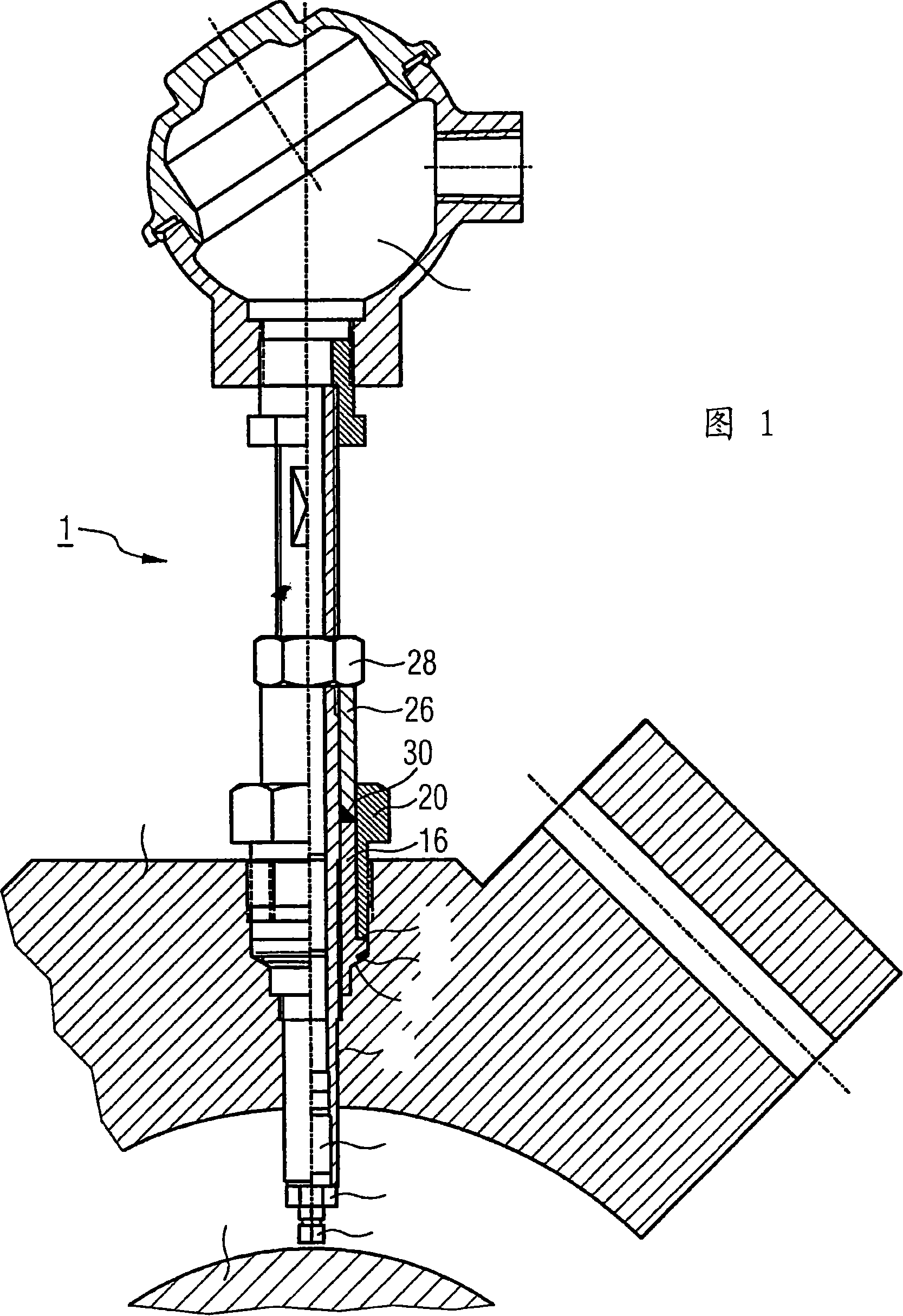
[0030] The probe holder system 1 according to FIG. 1 is provided for fastening a probe 2 on a housing 4 of a machine, not shown in detail. The probe 2 is used here for rotational speed measurement of a shaft 6 surrounded by a housing 4 , wherein the shaft 6 is mounted in oil O for friction reduction and cooling. The oil pressure prevailing inside the housing 4 exceeds the machine or ambient pressure outside the housing 4 . In order to achieve as high a measurement accuracy as possible during rotational speed measurement, the probe 2 is positioned at a relatively small radial distance of 1.5 mm from the axis 6, where the allowable tolerance is only ±0.1 mm.

[0031] The actual probe 2 or sensor is mounted at the end of a support rod 8 which is inserted from the outside into a corresponding hole 10 in the housing wall and can also be removed again for maintenance purposes. At the opposite end of the support rod 8 and the sensing head 12 there is a terminal 14 through which the ...


PUM


Abstract

A probe holder system (1) for fixing a probe (2) to a housing (4), wherein it is possible to provide a simple structure and position the probe (2) as accurately and easily as possible in relation to a measuring object. According to the invention, a housing bushing (16) provided with an inner thread and a carrier rod (8) for the probe (2), which can screwed into the threaded bushing (16), are provided. The threaded bushing can be placed in a reference position in an associated recess (10) of the housing wall and can be arrested by means of a locking element.

Description

technical field [0001] The invention relates to a probe clamping system for fixing the probe to the wall of the housing. Furthermore, the invention relates to a method for fastening such a probe holder system to a housing wall and a method for adjusting a probe mounted on such a probe holder system. Background technique [0002] Probes may be used for shaft monitoring in transmissions, engines, single shaft and variable speed compressors. Here, for example, shaft vibration measurements, rotational speed measurements or shaft condition measurements are performed. On the other hand, such probes usually comprise a sensing head mounted on a probe holder, which includes the sensor for the actual acquisition of the measured value. Said sensor itself is also often referred to as a probe in a narrow sense. The probe holder often has a rod-shaped or tubular design, so that it can be easily passed through the access hole in the housing around the axis to be monitored even in relati...

Claims


Application Information

Patent Timeline
Patent Type & Authority Applications(China)
IPC IPC(8): G01D11/30
CPCG01D11/30
Inventor 弗雷迪・詹兹文科・米库莱克
Owner SIEMENS AG
Why Eureka
Try Eureka