Gear transmission motor and robot gear transmission motor

A technology of gear transmission and motor, applied in the direction of transmission box, transmission parts, belt/chain/gear, etc., can solve the problems of high cost and lack of versatility, achieve large forming space, reduce assembly hours, and be easy to assemble. Effect

Active Publication Date: 2007-12-26
SUMITOMO HEAVY IND LTD
View PDF1 Cites 4 Cited by
  • Summary
  • Abstract
  • Description
  • Claims
  • Application Information

AI Technical Summary

Problems solved by technology

[0006] The geared motor disclosed in Patent Document 1 is a combination of a reducer with a specific reduction structure and a motor, and the reducer housing has a specific shape. , Insufficient versatility and high cost

Method used


Image

  • Gear transmission motor and robot gear transmission motor
  • Gear transmission motor and robot gear transmission motor
  • Gear transmission motor and robot gear transmission motor

Examples


Embodiment Construction

[0021] An example of an embodiment of the present invention will be described in detail below with reference to the drawings.

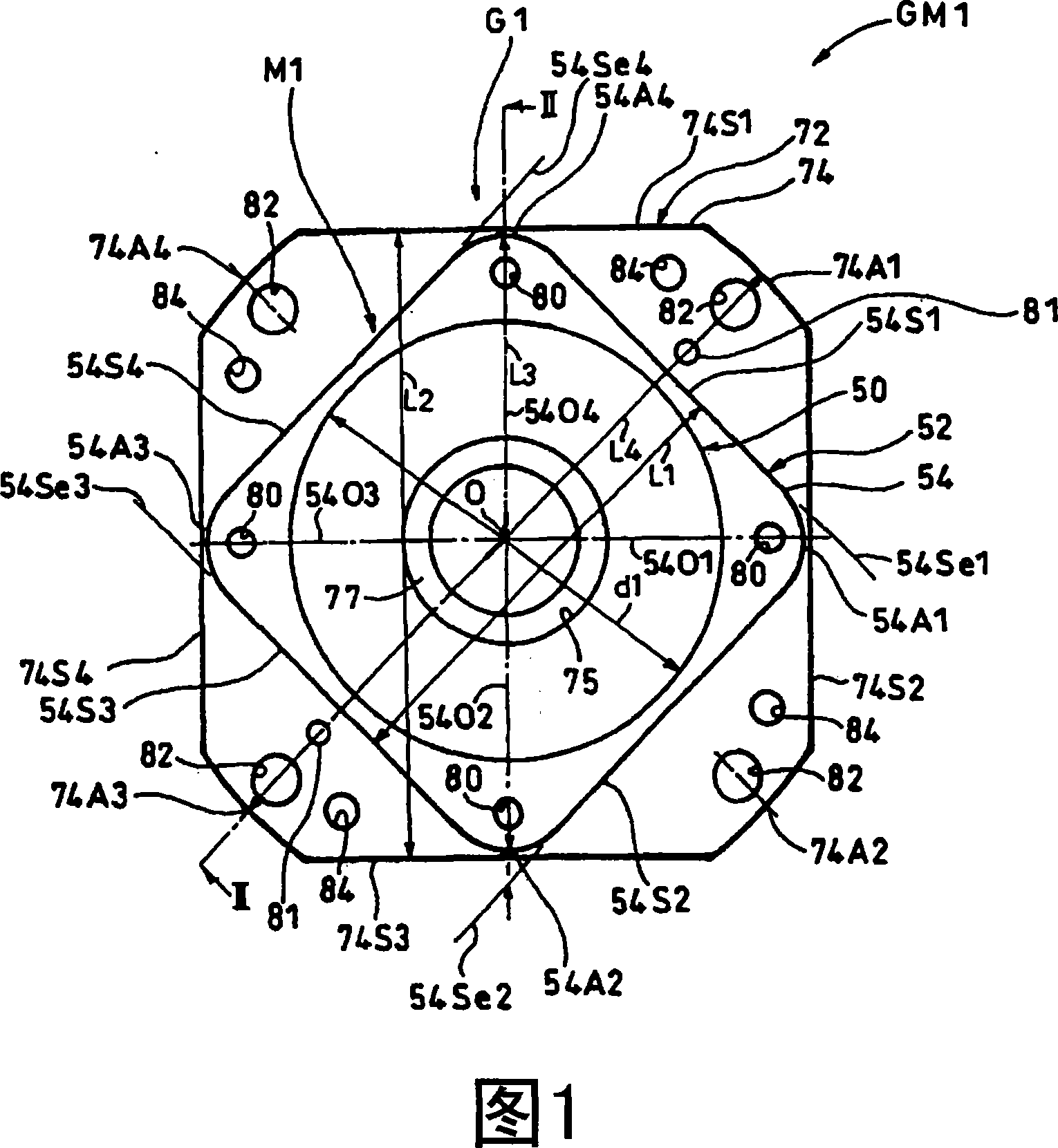
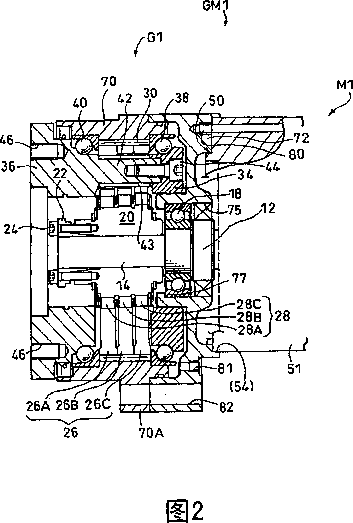
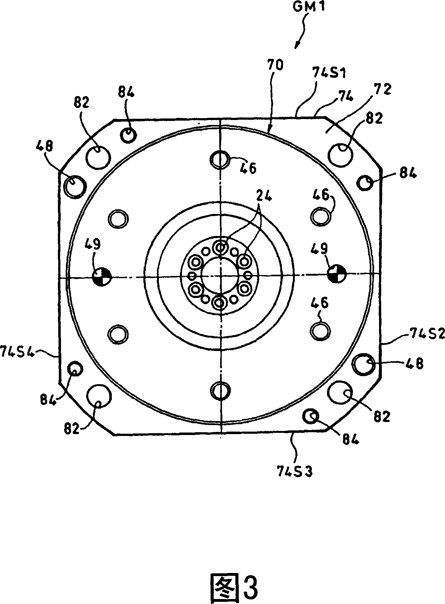
[0022] 1 to 3 show an example of a geared motor to which an embodiment of the present invention is applied.

[0023] This geared motor GM1 coaxially connects the motor M1 and the speed reducer G1, and is used for joint drive of an industrial robot (not shown). As shown in FIG. 2, the front-end|tip part of the motor shaft 12 of the motor M1 becomes the input shaft 14 of the speed reducer G1 directly. The housing main body 15 of the motor M1 does not close the parts on the reducer side (motor output side cover), and the reducer input side cover 72 (described later) also functions as an output side cover of the motor M1. A bearing 18 is assembled to a radially central portion of the reducer input side cover 72 , and the bearing 18 rotatably supports the motor shaft 12 (input shaft 14 ). In this embodiment, the reducer input side cover also functions as...


PUM


Abstract

Disclosed is a geared motor, which arranges the connecting hole and the mounting hole in reason and connects the motor and reducer organically, and is compact and easy to assemble and has an adequate connecting strength. The motor shell main body (the lateral end face of the reducer in the execution mode) and the reducer flange form a square. The square edge extended line of the motor shell main body is crossed to the square edge of the reducer flange. A motor connecting hole is disposed in the radial inner side of the square top for connecting the motor shell main body and the input lateral cover of the reducer (reducer flange). A installing hole is disposed in the corresponding position of the radial outer side of the square edge of the motor shell main body of the reducer flange for installing the reducer on the object machine.

Description

technical field [0001] The invention relates to a gear transmission motor and a gear transmission motor for a robot. Background technique [0002] Geared motors, which are widely used in applications such as joint drive of robots, are configured to output appropriate torque and rotation speed by connecting the motor to a reducer and decelerating the rotation of the motor by the reducer. [0003] In the field of geared motors, not limited to robot joint drive applications, it is highly desirable to have the smallest possible profile while obtaining the same output. From this point of view, Patent Document 1 discloses a geared motor configured to reduce the expansion of the speed reducer case in the width direction and to reduce the overall width as much as possible. [0004] In this geared motor, on the opposite surfaces of the casing surrounding the motor output shaft and the transmission gear of the reducer formed parallel to each other, there are formed shaft supporting p...

Claims


Application Information

Patent Timeline
IPC IPC(8): F16H57/02B25J19/00F16H57/023F16H57/025H02K5/04H02K7/116
CPCF16H57/025B25J19/00H02K5/04H02K7/116
Inventor 环诚广濑拓哉
Owner SUMITOMO HEAVY IND LTD
Why Eureka
Try Eureka