Resonance converter, and voltage stabilizing method for implementing light loading and idling load

A resonant converter, no-load technology, applied in high-efficiency power electronic conversion, output power conversion device, conversion equipment with intermediate conversion to AC, etc., can solve problems such as unstable circuit operation

Active Publication Date: 2007-12-26
DELTA ELECTRONICS INC
View PDF1 Cites 19 Cited by
  • Summary
  • Abstract
  • Description
  • Claims
  • Application Information

AI Technical Summary

Problems solved by technology

[0021] The main purpose of the present invention is to propose a resonant converter and its light-load and no-load voltage stabilization method to sol

Method used


Image

  • Resonance converter, and voltage stabilizing method for implementing light loading and idling load
  • Resonance converter, and voltage stabilizing method for implementing light loading and idling load
  • Resonance converter, and voltage stabilizing method for implementing light loading and idling load

Examples


Embodiment Construction

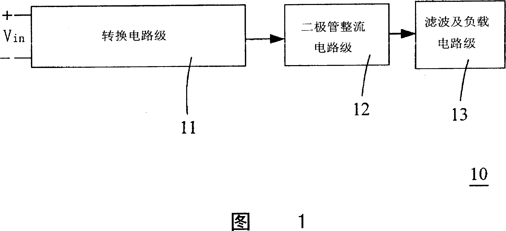
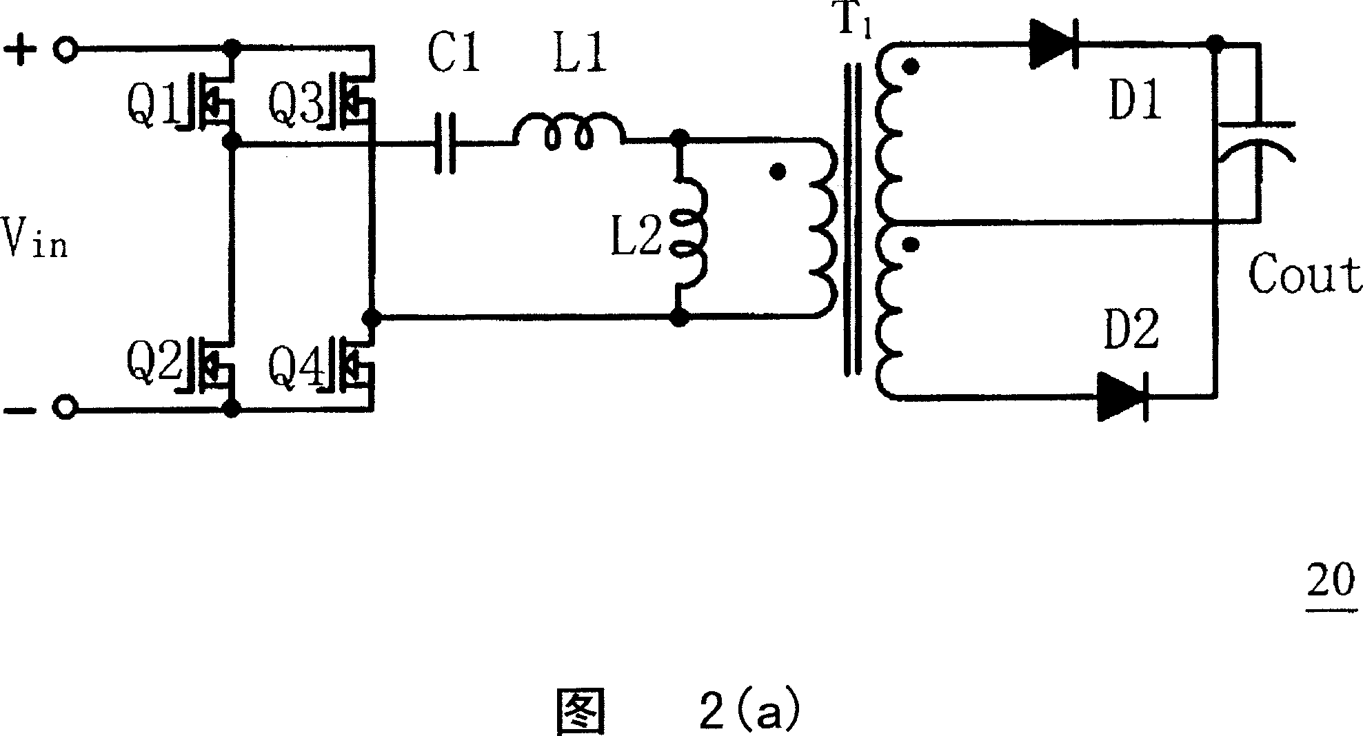
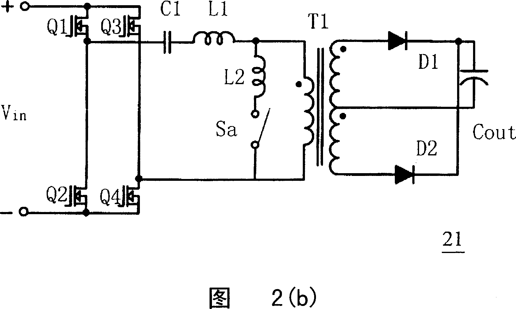
[0036] Please refer to FIG. 3 , which is a block diagram of a preferred embodiment of the present invention. In addition, in FIG. 3 , the same blocks as those in FIG. 1 are denoted by the same symbols. Wherein, the converter 30 is composed of a conversion circuit stage 11 , a diode rectification circuit stage 12 , a filter and load circuit stage 13 , a logic circuit 31 , a driver 32 and an energy feedback circuit 33 .

[0037] In FIG. 3 , the diode rectification circuit stage 12 is coupled in series to the conversion circuit stage 11 to rectify the output of the conversion circuit stage 11, and the filter and load circuit stage 13 is coupled in series to the diode rectification circuit stage 12 to rectify the output of the conversion circuit stage 11. The output of the diode rectification circuit stage 12 is filtered, the logic circuit 31 is coupled to the conversion circuit stage 11 in order to adapt to the conversion circuit stage 11 to generate a logic signal, and the drive...


PUM


Abstract

The resonance converter includes a stage of transfer circuit, a stage of diode rectification circuit, a stage of filtering and load circuit, a logic circuit, a drive and a power feedback circuit. When the stage of filtering and load circuit is in light load or zero load, the method feeds back energy to the stage of transfer circuit from the stage of filtering and load circuit.

Description

technical field [0001] The invention relates to a resonant converter and a method for realizing light-load and no-load voltage stabilization thereof, in particular to a resonant DC-DC converter applied to a power supply. Background technique [0002] The development trend of DC-DC converters, like most power supply products, is towards high efficiency (High Efficiency), high power density (High Power Density), high reliability (High Reliability) and low cost (Low Cost). . Please refer to FIG. 1, which is a block diagram of an existing DC-DC converter. In FIG. Its working principle is that the DC voltage Vin first passes through the conversion circuit stage 11 to receive high-frequency chopping, then passes through the diode rectification circuit stage 12 to receive rectification, and finally is sent to the filter and load circuit stage 13 to receive filtering and then to the load. [0003] In this kind of DC-DC converter, since the energy is transmitted from the conversion...

Claims


Application Information

Patent Timeline
IPC IPC(8): H02M3/28H02M7/06H02M7/217H02M1/14G05F1/56
CPCY02B70/1441Y02B70/10Y02P80/10
Inventor 曾剑鸿叶益青言超应建平尹国栋
Owner DELTA ELECTRONICS INC
Why Eureka
Try Eureka