
Screen printer and screen printing method

A technology of screen printing device and printing table, which is applied in the direction of screen printing machine, printing, printing machine, etc., can solve the problems of cost increase, complex transmission system, process complexity, etc., and achieve the effect of preventing contact

Active Publication Date: 2008-01-02
MURATA MFG CO LTD
View PDF1 Cites 15 Cited by
  • Summary
  • Abstract
  • Description
  • Claims
  • Application Information

AI Technical Summary

Problems solved by technology

[0010] (1) In the case of a large radius of curvature, a suction port is provided on the printing table, and the printed sheet can be fixed by suction, but in the case of a small curvature radius, air leakage will occur when the printed sheet is fixed, Therefore, the process of fixing the printed sheet on the printing table becomes complicated
It is also conceivable to add force to the printed sheet to fix and maintain the printed sheet. However, it is not easy to apply sufficient force without contacting the printed undried printed pattern, and a complicated conveying system is necessary.
[0011] (2) In the case of using a printing table with a small radius of curvature, in order to prevent the printed pattern from contacting the printing mask, the printed sheet must be drawn out obliquely downward. In the case of sending it to the drying oven, etc., the drying oven must be installed at an angle, or a complicated conveying system that can change the conveying direction of the printed printed sheet must be used, resulting in a complication of the process or an increase in cost.

Method used


Image

  • Screen printer and screen printing method
  • Screen printer and screen printing method
  • Screen printer and screen printing method

Examples


Embodiment 1

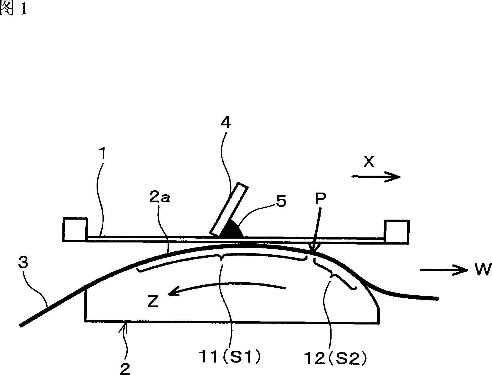
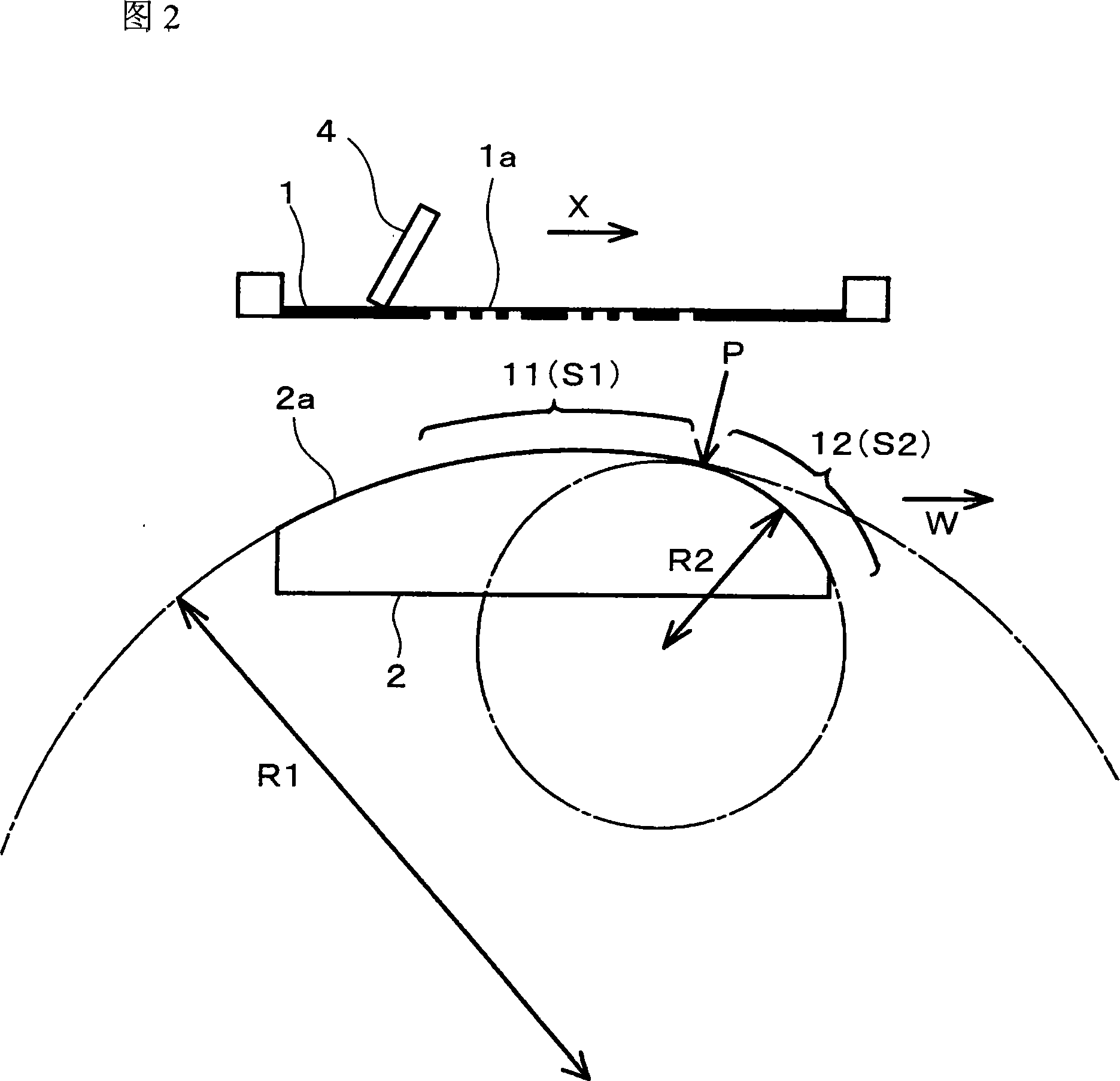
[0079] FIG. 1 is a diagram showing a screen printing apparatus of one embodiment of the present invention. This screen printing device is provided with printing mask 1, printing table 2 and squeegee 4; The surface (upper surface) 2a of printing table 2 opposite to printing mask 1 has convex curved surface shape, and printing table 2 is rotatable, So that its predetermined area can face the printing mask 1; the squeegee 4 presses the printing mask 1 on the printed matter 3 placed on the upper surface (opposite surface) 2a of the printing table 2, and simultaneously prints Slide on Mask 1.

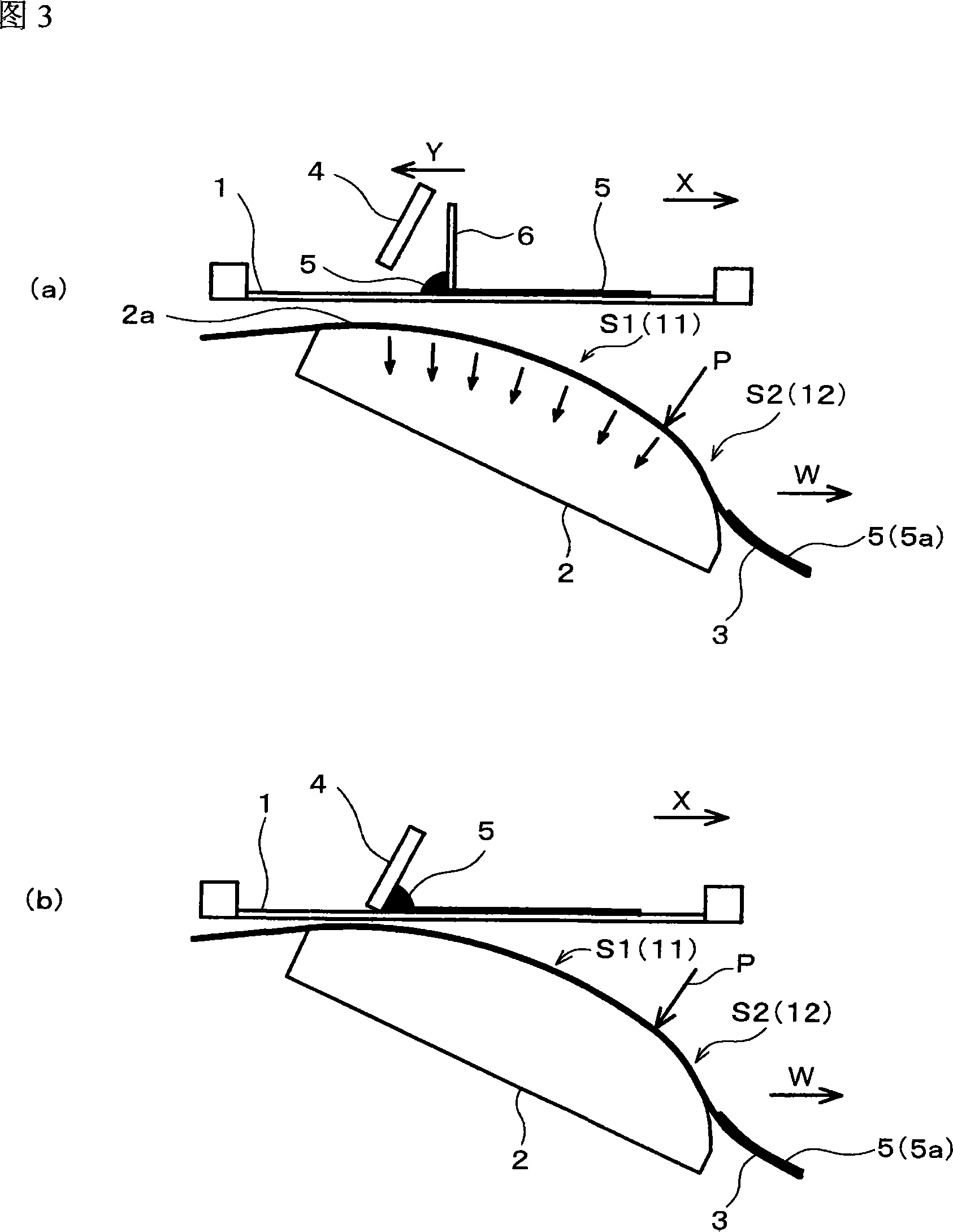
[0080] In this screen printing device, when the squeegee 4 slides on the printing mask 1, the printing table 2 rotates, and the printing area of ​​the elongated object 3 to be printed on the upper surface 2a of the printing table 2 is abutted against In the area corresponding to the sliding position of the squeegee 4 of the printing mask 1 , the pushing force of the squeegee 4 presses the p...

Embodiment 2

[0098] Fig. 5(a) is a configuration diagram of a main part of a screen printing device according to another embodiment (embodiment 2) of the present invention. As shown in Figure 5 (a), in the screen printing device of this embodiment 2, the surface (upper surface) 2a of the printing table 2 facing the printing mask 1 corresponds to the position of the squeegee 4 on the printing mask. The area S1 of the squeegee sliding portion (squeegee sliding area) 11 that slides on the mold 1 has an arc-shaped cross-sectional shape, but the area of ​​the printing table 2 corresponding to the end of the sliding of the squeegee 4 on the printing mask 1 is In the region S2 of the squeegee non-sliding portion 12 of the printing end portion P (near the squeegee sliding end portion) S2, a notch 13 is formed such that the upper surface 2a of the printing table is cut away.

[0099] Use the screen printing device that has formed the printing table 2 of gap 13 on the upper surface 2a like this, mak...

Embodiment 3

[0103] Fig. 6 is a configuration diagram of main parts of a screen printing device according to another embodiment (embodiment 3) of the present invention. As shown in FIG. 6, in the screen printing device of this embodiment 3, the surface (upper surface) 2a of the printing table 2 facing the printing mask 1 corresponds to the position of the squeegee 4 on the printing mask 1. The cross section of the area S1 of the sliding squeegee sliding portion (squeegee sliding area) 11 has an arc-like shape corresponding to the end portion of the area S1 of the squeegee sliding portion (squeegee sliding area) 11, that is, the scraper. The ink plate sliding terminal portion P is configured as an end portion (terminal portion) of the printing table 2 .

[0104] Using a screen printing device having a printing table 2 whose terminal portion corresponding to the area S1 of the squeegee sliding portion 11 constitutes the terminal portion of the printing table 2, the area S1 corresponding to t...


PUM


Abstract

A screen printer and a screen printing method in which a matter being printed on can be utilized effectively while print reliability is secured by preventing contact between a print mask and the matter being printed on without increasing the interval (gap) between print areas. Curvature (R1) of that region S1 on a print base (2) corresponding to a squeegee slide section (11) where a squeegee (4) slides on a print mask (1) is set larger than the curvature (R2) of that region S2 on the print base (2) corresponding to a squeegee non-slide section (12) contiguous to a print end portion P where sliding of the squeegee (4) on the print mask (1) ends. When a matter (3) being printed on is carried reversely to the carrying direction W, the curvature (R1) of that region on the print base (2) corresponding to the squeegee slide section (11) is set larger than the curvature (R2) of that region corresponding to a squeegee non-slide portion contiguous to a print start portion where sliding of the squeegee (4) on the print mask (1) is started.

Description

technical field [0001] The present invention relates to a screen printing device and a screen printing method. Specifically, it relates to a screen printing device and a screen printing method used when, for example, printing an electroconductive paste on a ceramic green sheet or the like. Background technique [0002] For example, in the manufacturing process of laminated ceramic electronic components, when a conductive paste is printed on a laminated ceramic green sheet to form an internal electrode pattern, as a method of obtaining a predetermined pattern (printed pattern), the screen printing method is used. widely used. [0003] What Fig. 7 (a), (b), (c) showed is an example of the conventional screen printing method. The screen printing device used here is provided with: a printing mask 51 with openings to form a predetermined pattern, a squeegee 52 that moves while pressing the printing paste 54 placed on the printing mask 51, and a cross-sectional shape of the upper...

Claims


Application Information

Patent Timeline
Patent Type & Authority Applications(China)
IPC IPC(8): B41F15/26H05K3/12B41F15/08
CPCB41F15/0831H05K1/0393H05K3/1216H05K2201/09018
Inventor 田上三花
Owner MURATA MFG CO LTD
Learn More