False proof structure used for card and certificate and its identifying method

An identification method and card technology, which is applied in the field of card anti-counterfeiting technology and public safety, can solve the problems of long detection time, inappropriateness, and high cost of anti-counterfeiting

Inactive Publication Date: 2008-01-09
SVG TECH GRP CO LTD +1
View PDF1 Cites 19 Cited by
  • Summary
  • Abstract
  • Description
  • Claims
  • Application Information

AI Technical Summary

Problems solved by technology

However, the authenticity of cards using chip technology needs to be identified by professional testing instruments and personnel with professional skills. The cost of anti-counterfeiting is high and the detection time is long.
Especially for g

Method used


Image

  • False proof structure used for card and certificate and its identifying method
  • False proof structure used for card and certificate and its identifying method
  • False proof structure used for card and certificate and its identifying method

Examples


Embodiment 1

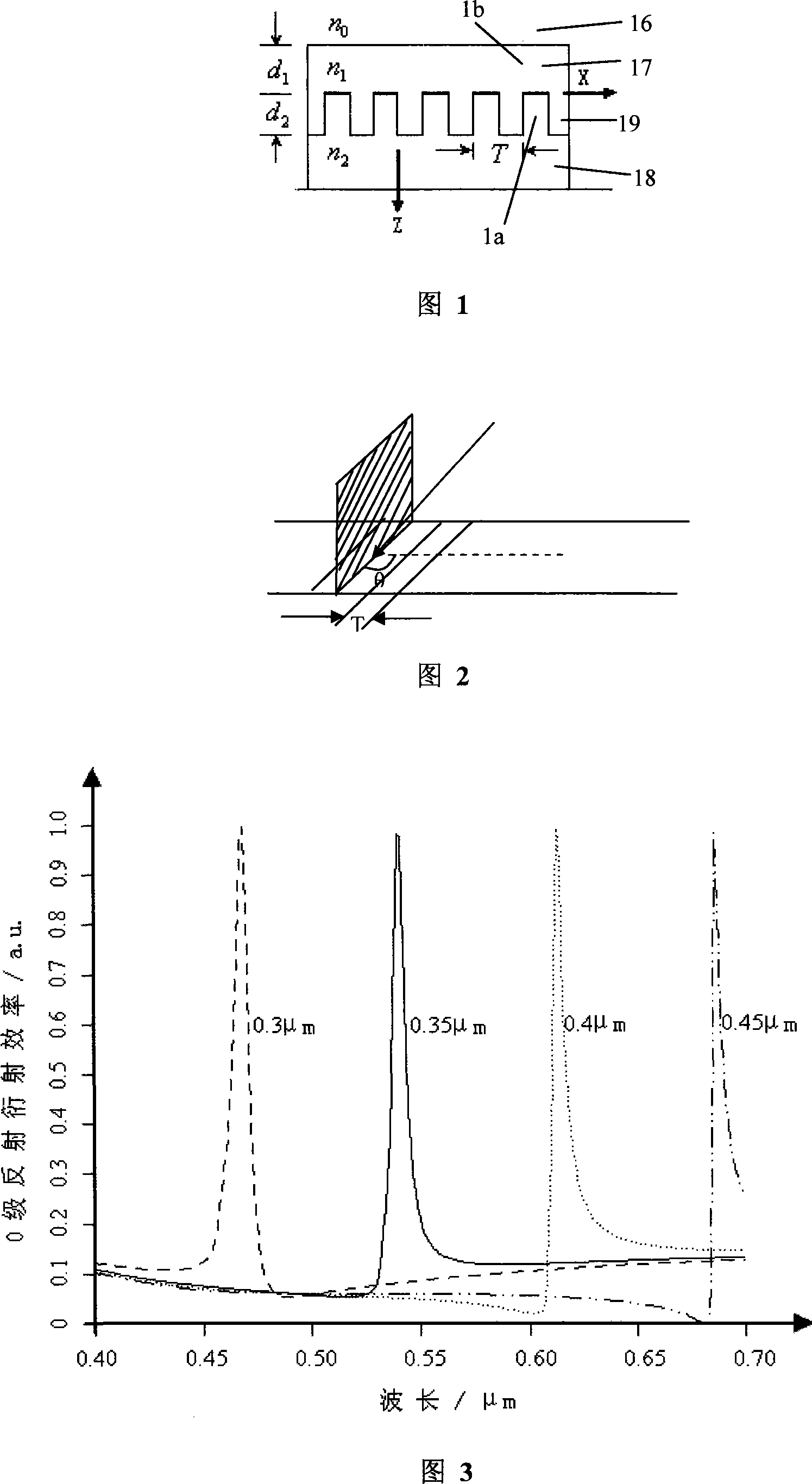
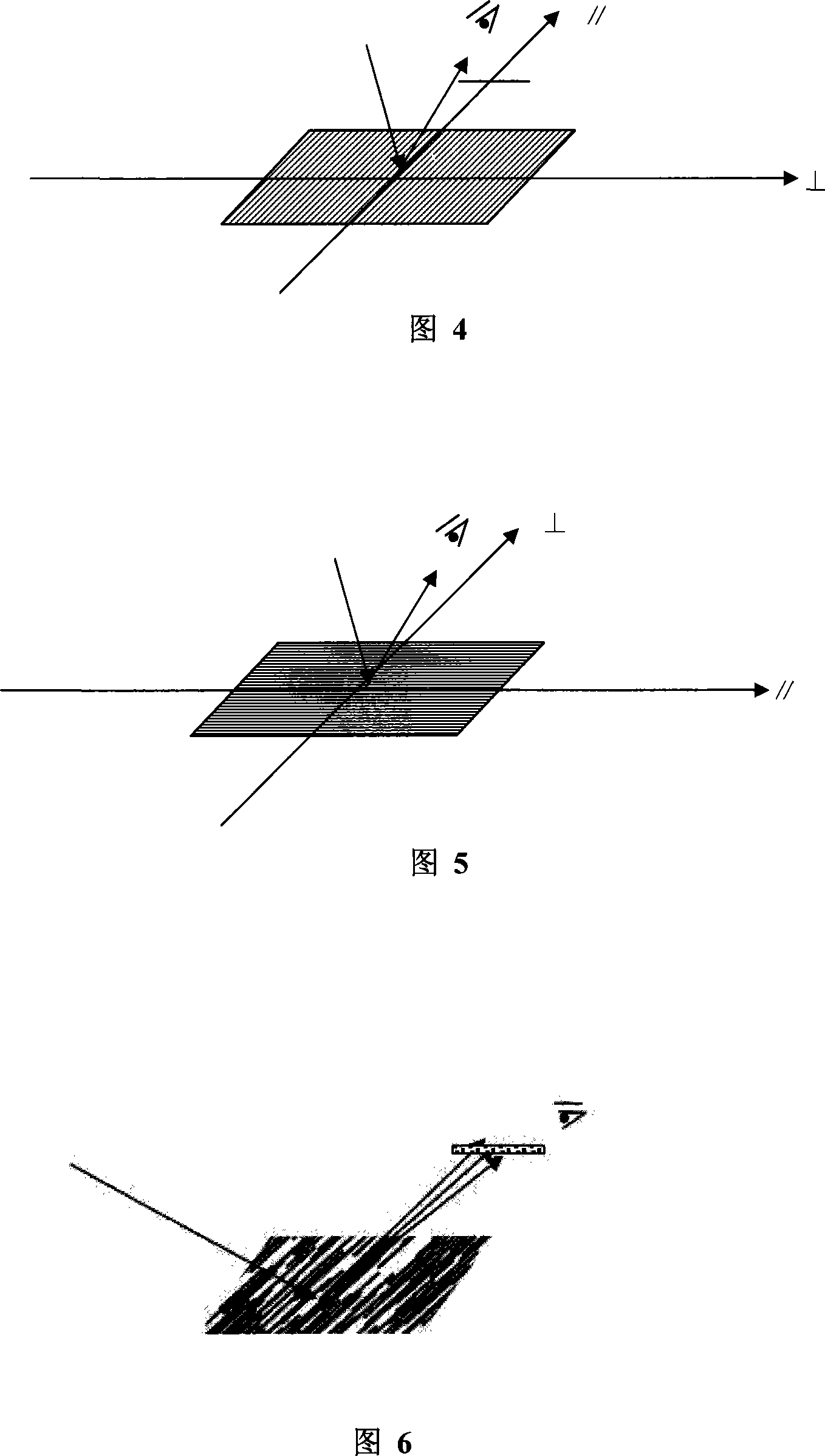
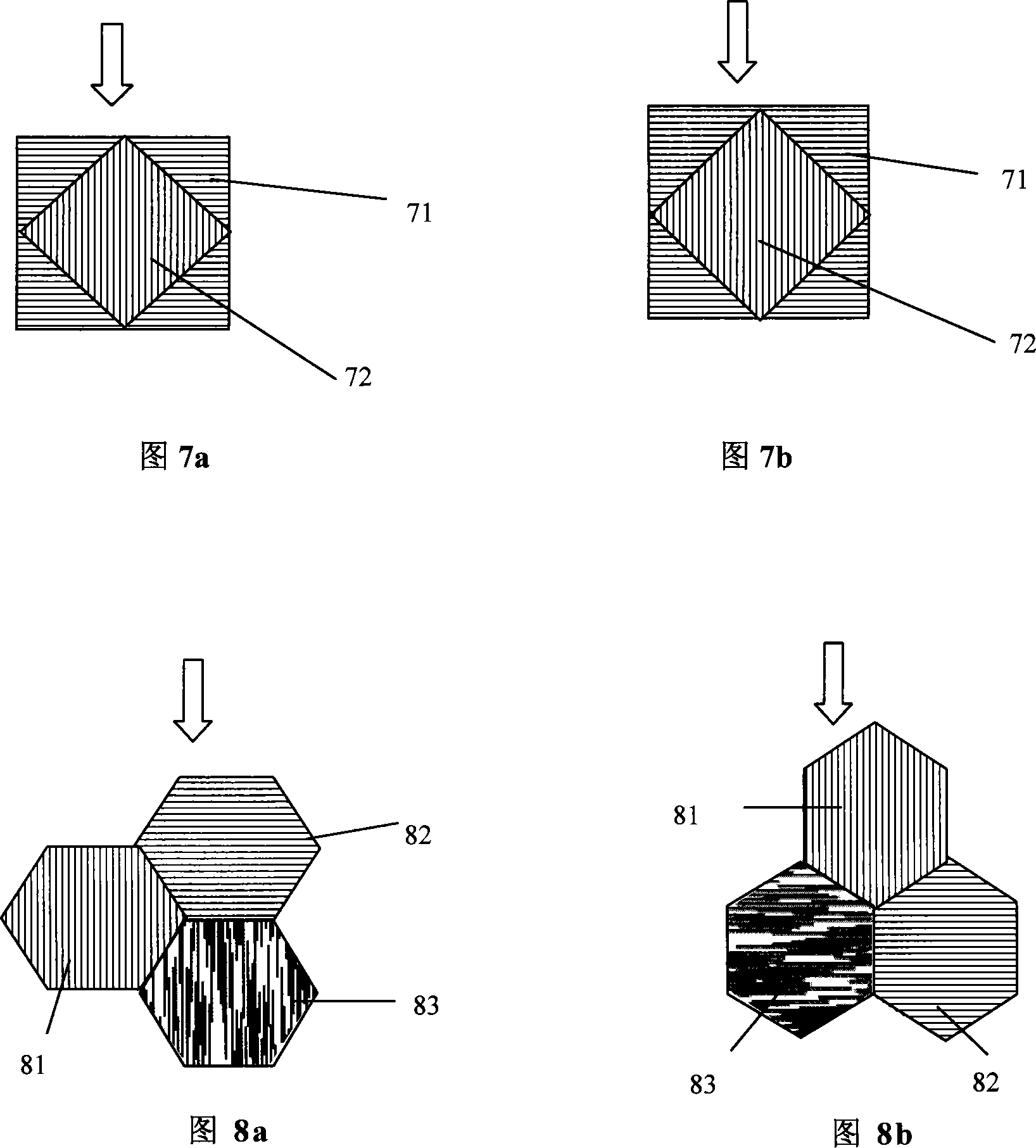
[0064] Embodiment 1: An anti-counterfeit structure for a card. On the body of the card to be anti-counterfeited, an identification pattern composed of a grating structure is provided. The identification pattern includes at least two types of graphic areas, and the two types of graphic areas are The orientation of the grating structure is arranged orthogonally to form a dual visual channel, and the two graphic areas do not overlap each other; the grating period of the grating structure is 300-500 nanometers, the groove depth is 50-150 nanometers, and the grating structure is filled with A transparent high-refractive index medium layer, the thickness of the medium layer is 20-30 nanometers, and the refractive index of the medium is greater than 1.6. The microstructure can be made by electron beam or laser beam lithography technology, and the high refractive index medium can be made by vacuum coating technology.

[0065] Referring to Figure 7a, this image is a schematic diagram o...

Embodiment 2

[0066] Embodiment 2: An anti-counterfeiting structure for a card. On the body of the card to be anti-counterfeited, an identification pattern composed of a grating structure is provided. The identification pattern includes at least two types of graphic areas, and the two types of graphic areas are The orientation of the grating structure is arranged orthogonally to form a dual visual channel, and the two graphic areas do not overlap each other; the grating period of the grating structure is 300-500 nanometers, the groove depth is 50-150 nanometers, and the grating structure is filled with A transparent high-refractive index medium layer, the thickness of the medium layer is 20-30 nanometers, and the refractive index of the medium is greater than 1.6. There is a third graphic area, which is composed of microstructured graphics with directional scattering characteristics. The line width of the grating structure that constitutes the microstructured graphics varies randomly within ...


PUM

PropertyMeasurementUnit
Grating periodaaaaaaaaaa
Thicknessaaaaaaaaaa

Abstract

The present invention discloses anti-fake structure for cards, and the anti-fake card is provided with mark pattern comprising raster structure and features that the mark pattern includes at least two kinds of pattern areas with orthogonally arranged raster structures to constitute double visual channels. The raster structures have period of 300-500 nm, slot depth of 50-150 nm and filled transparent high refractive index dielectric layer of 20-30 nm thickness and refractive index higher than 1.6. The pattern of the present invention has obvious visual characteristic capable of being recognized easily and convenient identification of the truth. The micro anti-fake structure has structural data calculated based on strict coupled wave theory, is made by means of advanced electronic beam or laser beam interference photoetching technology, and possesses high safety.

Description

technical field [0001] The present invention relates to the fields of card anti-counterfeiting technology and public safety, in particular to an anti-counterfeiting structure for cards realized by using a grating image, which has a visual effect of color conversion, and is applicable to the public's visual recognition and anti-counterfeiting, especially for national statutory certificates Or card anti-counterfeiting security. Background technique [0002] At present, the counterfeiting of valid documents related to public safety is becoming more and more obvious, such as securities, certification marks, legal documents and certificates in various industries, etc. lack effective and high-tech anti-counterfeiting and visual identification means. [0003] Many enterprises and relevant departments are adopting some anti-counterfeiting technologies, such as two-dimensional bar codes, laser holographic markings, anti-counterfeiting ink printing, etc. However, with the popularizati...

Claims


Application Information

Patent Timeline
IPC IPC(8): B44F1/12G06K9/00B42D25/324B42D25/328
Inventor 罗俊仪虞力英包勇强邵咏秋陈林森周小红浦东林叶燕邵洁吴智华
Owner SVG TECH GRP CO LTD
Why Eureka
Try Eureka