Attachment structure

A technology for connecting structures and components, which is applied in the direction of handwheels, steering controls installed on vehicles, handlebars, etc., can solve the problems of collision between the rotary connector device 81 and the combination switch 86, damage to the locking claw, and detachment, so as to promote Operability and fixation reliability, effective connection, and the effect of improving accuracy

Inactive Publication Date: 2008-01-09
YAZAKI CORP +1
View PDF3 Cites 8 Cited by
  • Summary
  • Abstract
  • Description
  • Claims
  • Application Information

AI Technical Summary

Problems solved by technology

[0014] However, according to the above-mentioned structure of coupling the rotary connector device and the combination switch of FIG. 76, therefore, many screw members 90, 91 and many joining steps are required
[0015] In addition, according to the structure of the prior art coupling the rotary connector device and the combination switch in FIG. Due to repeated coupling and separation, the locking claws 83, 88 are destroyed or the fixing force of the locking claws 83, 88 is weakened, so that the rotary connector device 81 and the combination switch 86 collide or disengage.

Method used


Image

  • Attachment structure
  • Attachment structure
  • Attachment structure

Examples


Embodiment Construction

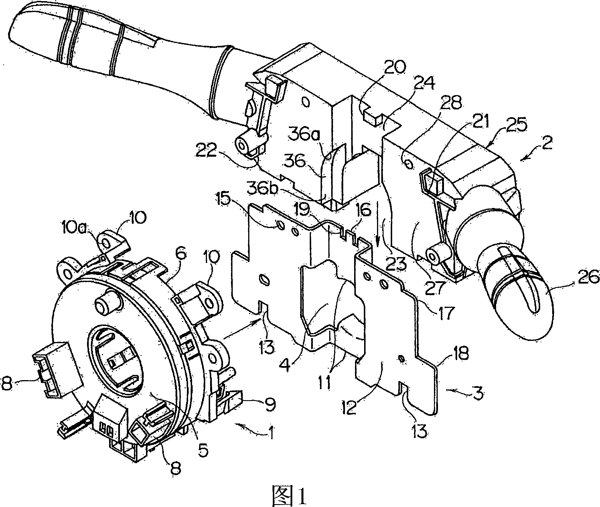
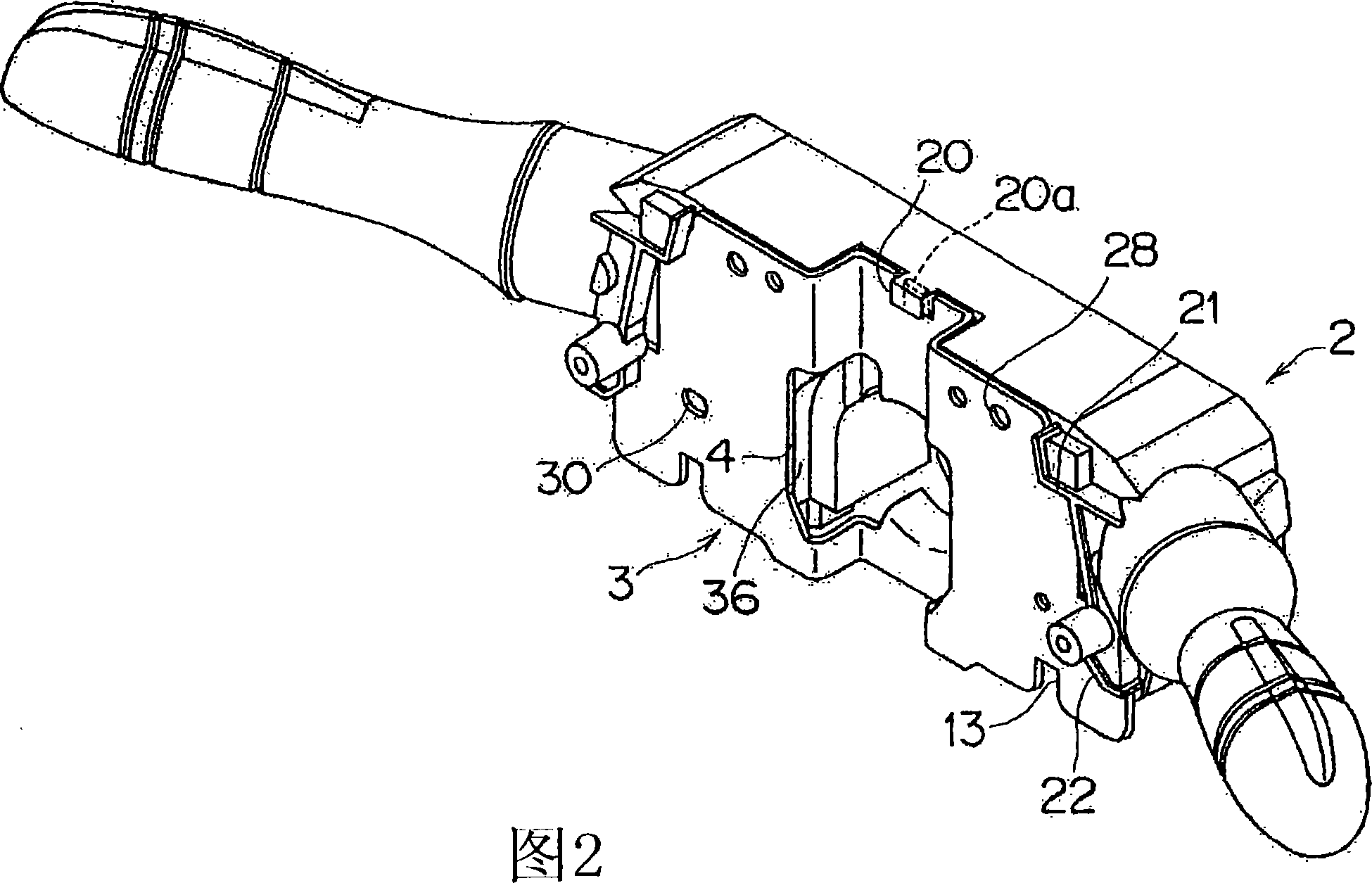
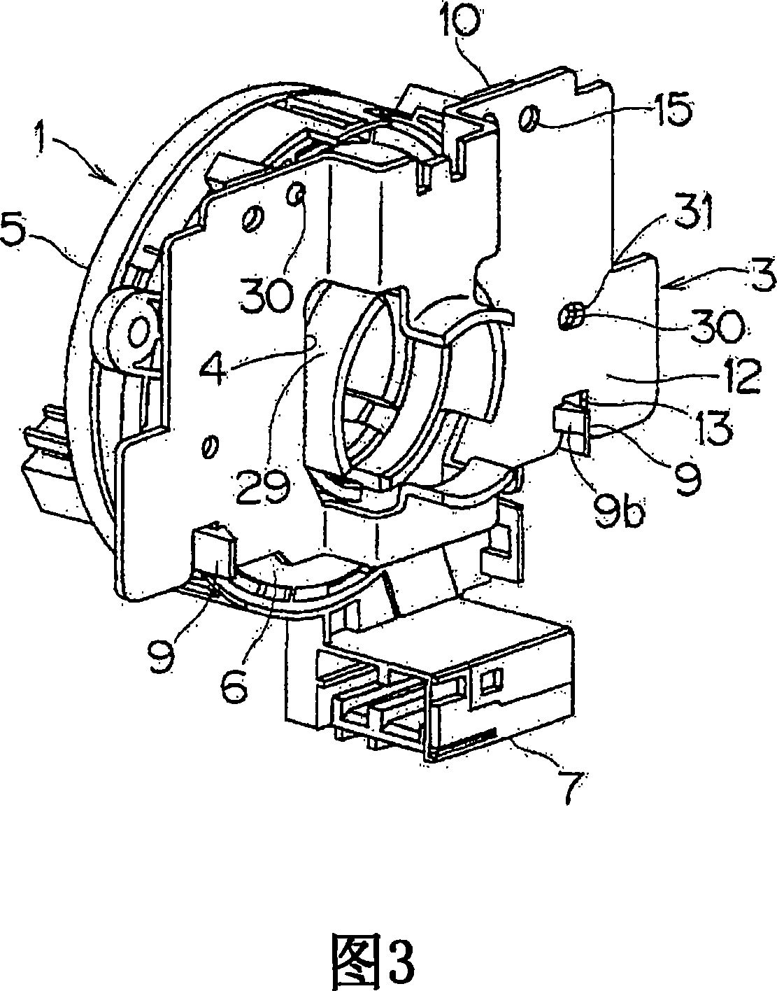
[0050] 1 to 5 show an embodiment of a structure coupling a rotary connector device and a combination switch according to the present invention.

[0051]As shown in FIG. 1 , the rotary connector device 1 and the combination switch 2 are fixed to each other by a bracket 3 . A steering shaft (not shown) is inserted into a hole portion 4 at the center of the bracket 3, and the combination switch 2 is fixed to a resin cover (not shown) which is cylindrical around the steering wheel.

[0052] In the basic structure of the rotary connector device 1, a substantially helical flat wire harness (not shown) is contained in the inner side of a case including a fixed cover 6 and a rotary cover 5, both of which are ring-shaped and made of synthetic resin. production. One end of the flat wire harness is connected to a connector 7 ( FIG. 3 ) on the side of the fixed cover, and the other end of the flat wire harness is connected to a connector 8 on the side of the rotating cover.

[0053] As ...


PUM


Abstract

An attachment structure includes a bracket that is arranged around a steering, a rotary connector device that has an engagement portion for being provisionally fixed to the bracket in a provisionally fixed state, and a combination switch that has a guide portion for being slidably retained to the bracket in the provisionally fixed state. The rotary connector device and the combination switch are completely fastened together with the bracket by a screw member from the provisionally fixed state.

Description

technical field [0001] The present invention relates to an attachment structure for coupling a rotary connector device and a combination switch for fixing the combination switch and the rotary connector arranged around a steering wheel of a vehicle to each other through a bracket. Background technique [0002] FIG. 8 shows a rotary connector in the prior art (refer to Patent Document 1). [0003] The rotary connector device 61 is arranged near the steering wheel 62 of the vehicle, and includes an annular rotary cover 64 fixed to the steering shaft 63, an annular fixed cover 65 fixed to the combination switch 69 on the outer side of the steering shaft 63, and The interior of the annular space 66 surrounded by the two covers 64, 65 is a flexible flat wire 67 wound in a substantially helical shape. [0004] A roller 68 is rotatably provided in the circular space 66 , and flat harnesses 67 are arranged along the inner peripheral wall of the rotary cover 64 and the outer periphe...

Claims


Application Information

Patent Timeline
Patent Type & Authority Applications(China)
IPC IPC(8): B60R16/02B62D1/04
CPCB60Q1/1469B62D1/10B62D1/12
Inventor 三井隆彦関野豊
Owner YAZAKI CORP
Why Eureka
Try Eureka