Support structure for control pedal

A technology for supporting structures and pedals, which is applied in the direction of superstructure, superstructure sub-assembly, control components, etc., and can solve the problems of the support shaft of the operating pedal falling off, the operating pedal falling off, etc.

Inactive Publication Date: 2008-01-09
オートテクニカ +1
View PDF1 Cites 14 Cited by
  • Summary
  • Abstract
  • Description
  • Claims
  • Application Information

AI Technical Summary

Problems solved by technology

[0006] In the technical solutions described in the above-mentioned patent documents 1 and 2, in normal times (when no collision occurs), the fulcrum of the operating pedal is supported on the pedal with a predetermined support strength. When the driver performs an excessive stepping operation on the pedal and a large downward load acts on the operating pedal, the pivot of th...

Method used


Image

  • Support structure for control pedal
  • Support structure for control pedal
  • Support structure for control pedal

Examples


Embodiment Construction

[0029] Hereinafter, preferred embodiments of the present invention will be described with reference to the drawings.

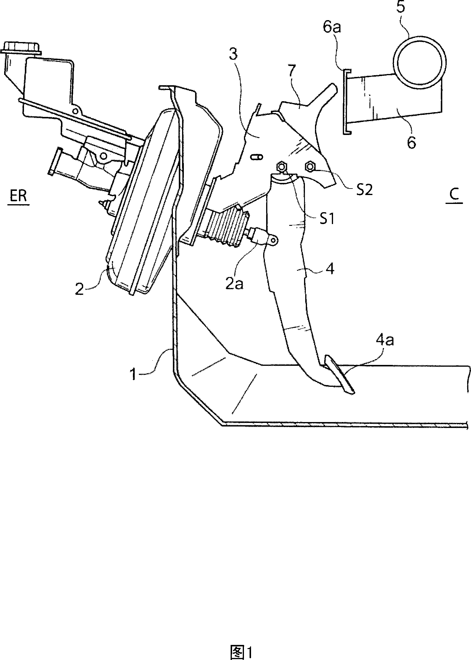
[0030] FIG. 1 is a side view schematically showing an operation pedal support structure according to an embodiment of the present invention. In FIG. 1 , reference numeral 1 denotes a dash panel, an engine room ER is formed in front of it, and a vehicle compartment C is formed in the rear thereof. On the dash panel 1, a brake booster 2 is installed on the side of the engine room ER, and a pedal bracket 3 is installed on the side of the vehicle compartment C. Freely rocking brake pedal 4. Same as the conventional structure, the brake booster 2 is connected to the brake pedal 4 through the push rod 2a, and the brake pedal 4 is stepped forward by the driver (not shown) on the pedal foot provided at the lower end of the brake pedal 4. The pedal 4a is operated to swing forward about the first support shaft S1 at the upper end thereof, thereby pushing the push rod ...


PUM


Abstract

Disclosed is a support structure for a vehicle control pedal, which comprises a pedal bracket (3) supporting the control pedal (4) through a first support shaft (S1) inserted through a support hole (303), a swingable lever (7) adapted to, during a vehicle collision, come into interference with a vehicle body member (6) so as to be swingingly moved about a second support shaft (S2) while pushing the first support shaft (S1) downwardly to allow the first support shaft (S1) to drop out of the support hole (303), and a drop-out restriction member (8) engaged by a pin member (20) and coupled to the swingable lever (7) in a relatively unswingable manner, so as to restrict the drop-out of the first support shaft (S1). The support structure is designed such that, according to the swing movement of the swingable lever (7) during the vehicle collision, the restriction on drop-out of the first support shaft (S1) by the drop-out restriction member (8) is removed to allow the first support shaft (S1) to drop out of the support hole (303). The support structure of the present invention can prevent impact energy during a vehicle collision from being input to a leg of a driver through the control pedal while reliably restricting accidental drop-out of the control pedal in a normal condition.

Description

technical field [0001] The present invention relates to a support structure for an operating pedal. Background technique [0002] Operating pedals, such as a brake pedal and a clutch pedal, which are rocked by the driver's feet, are generally supported on the dash panel by a pedal bracket. That is, by fixing the pedal bracket to the dash panel, and by pivotally supporting the upper end portion of the operation pedal on the pedal bracket through the first pivot extending along the vehicle width direction, the above-mentioned operation pedal is supported swingably. on the cowl. With such an operation pedal structure, when the vehicle collides (during a frontal collision), the collision energy will be applied to the driver's feet through the operation pedal. structure. [0003] As a technology that satisfies the above-mentioned requirements, for example, the technical solution disclosed in Japanese Patent Laid-Open Publication No. 2005-510785 (hereinafter referred to as Pate...

Claims


Application Information

Patent Timeline
IPC IPC(8): B60R21/09B60T7/06B62D25/08G05G1/327
Inventor 德毛雅之日浦哲男石田博文
Owner オートテクニカ
Why Eureka
Try Eureka