Bicycle

A bicycle and frame technology, applied in the driving field of wheeled devices, to achieve the effects of fast forward speed, strong entertainment, and labor-saving riding

Inactive Publication Date: 2010-10-06
SHANGHAI HI TECH ROBOT
View PDF0 Cites 2 Cited by
  • Summary
  • Abstract
  • Description
  • Claims
  • Application Information

AI Technical Summary

Problems solved by technology

[0010] It can be seen from the above formula that in the traditional wheeled device driven by the pedal sprocket, only 63.7% of the active force F from the human leg forms the moment that drives the wheeled device forward on average , 36.3% is wasted

Method used


Image

  • Bicycle
  • Bicycle
  • Bicycle

Examples


Embodiment Construction

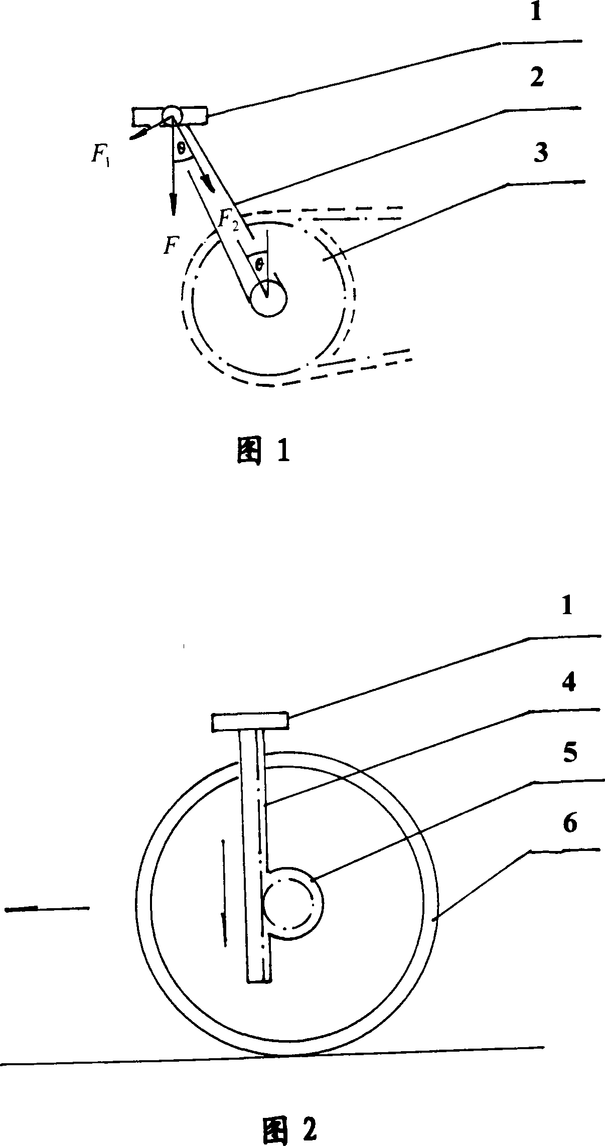
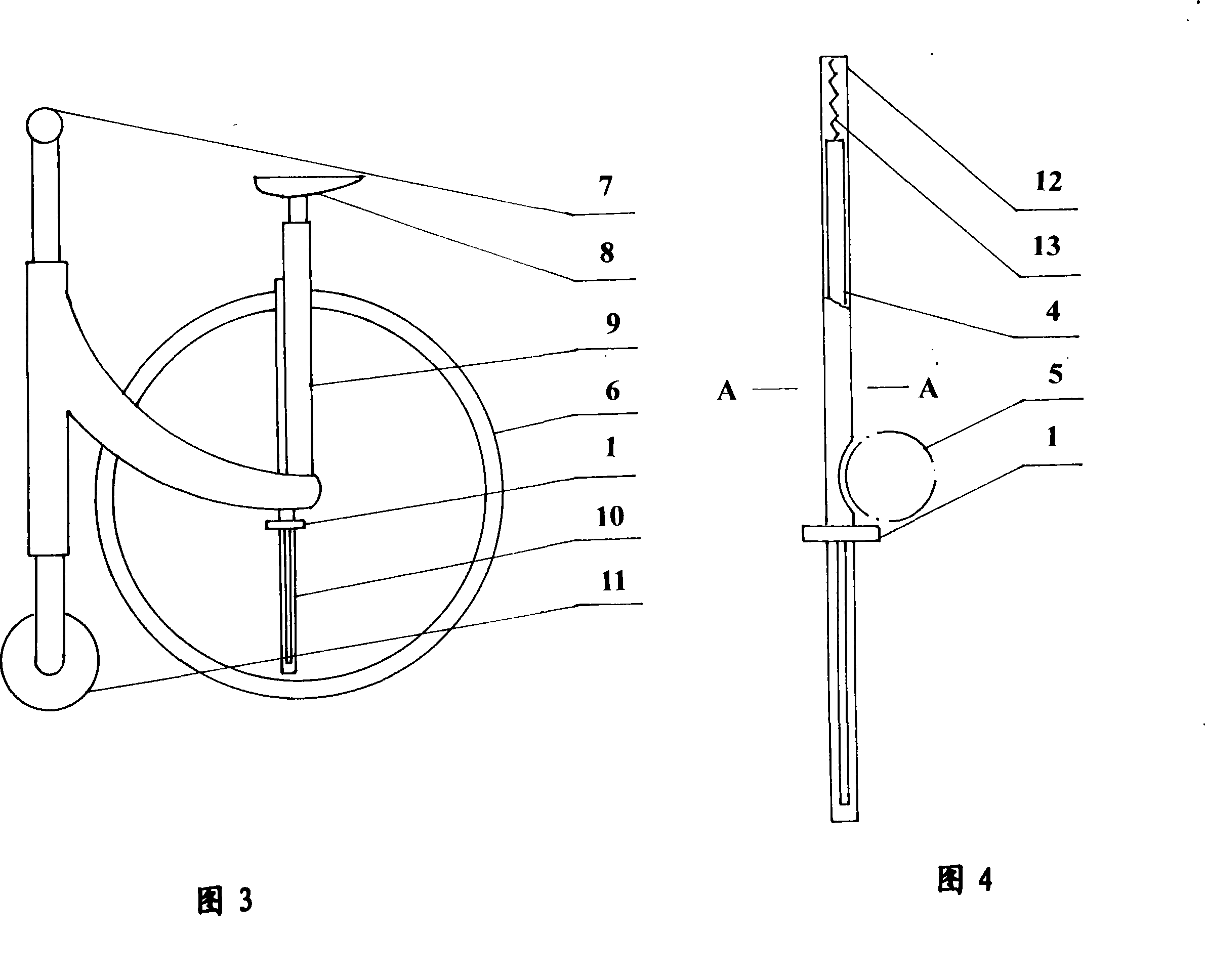
[0030] please see figure 2 , figure 2 A method of driving a wheel-type device with a linear motion rack is shown. In the figure, 1 is a pedal, 4 is a rack, 5 is a ratchet, and 6 is a wheel. The structure of the ratchet wheel 5 is the same as that of the ratchet wheel fixed on the rear axle of the traditional bicycle, and the rotation direction of the ratchet wheel 5 and the traditional bicycle ratchet wheel is also the same: that is, when the rack 4 is engaged on the left side of the ratchet wheel 5, the rack 4 downward The moving ratchet 5 drives the wheel to rotate, so that the wheel 6 rolls forward, and the upward movement of the ratchet 5 by the rack 4 does not affect the normal rotation of the wheel 6 .

[0031] figure 2 In the rack drive wheel type device shown, the installation direction of the rack 4 is perpendicular to the ground, the upper end of the rack 4 is fixed with the pedal 1 , and the rack 4 is engaged with the left side of the ratchet 5 . The human's l...


PUM


Abstract

The present invention relates to wheeled equipment driving technology, and is especially one wheeled equipment driving method and bicycle driven in the said method. The present invention features that the wheeled equipment with driving wheel possessing a ratchet wheel is driven with one linearly moving gear rack. The bicycle driven in the said method may have all the force from the legs become the moment for moving forwards and mechanical efficiency higher than traditional chain wheel driven bicycle. Therefore, the bicycle driven with the linearly moving gear rack has force saving, high speed, high recreation effect and good body building effect.

Description

technical field [0001] The invention relates to the driving technology of a wheeled device, in particular to a bicycle. Background technique [0002] Bicycles have been around for over 200 years and have undergone many changes. In 1885, the British invented a bicycle with the same size as the front and rear wheels, and placed the sprocket with crank and pedals in the middle of the front and rear wheels. The person pedals, the crank drives the sprocket, and the sprocket drives the rear wheel to rotate through the chain to drive the bicycle forward. People's feet push down on the pedals, the pedals make a circular motion, and the mode that the sprocket drives the bicycle forward through the chain has not changed so far. This driving mode is widely used in wheeled devices such as bicycles and human-powered tricycles. [0003] Now analyze the efficiency problem of the pedal sprocket drive system. please see figure 1 , figure 1 It is a schematic diagram of the force anal...

Claims


Application Information

Patent Timeline
Patent Type & Authority Patents(China)
IPC IPC(8): B62M1/04B62M23/00B62K3/00B62M1/24
CPCB62M1/18
Inventor 金起农
Owner SHANGHAI HI TECH ROBOT
Why Eureka
Try Eureka