Control system used for motor with auxiliary device and control method thereof

A technology of auxiliary equipment and control system, applied in the direction of engine control, control system, combustion engine, etc.

Inactive Publication Date: 2008-01-09
DENSO CORP
View PDF1 Cites 22 Cited by
  • Summary
  • Abstract
  • Description
  • Claims
  • Application Information

AI Technical Summary

Problems solved by technology

[0008] The present invention has been accomplished in view of the above-mentioned problems, and its object is to provide a control system for an engine with auxiliary equipment, the control system of which controls the auxiliary equipment in the presence of malfunctions that can adversely affect the engine torque control. Under the circumstances, it can reduce the adverse effect caused by the failure on the engine torque control. The purpose of the present invention is to provide a method for controlling the engine with auxiliary equipment, so that even if there is a fault that may cause adverse effects on the engine torque control. Executes correct control of the engine with optimum efficiency even in the event of a system failure affecting the

Method used


Image

  • Control system used for motor with auxiliary device and control method thereof
  • Control system used for motor with auxiliary device and control method thereof
  • Control system used for motor with auxiliary device and control method thereof

Examples


no. 1 example

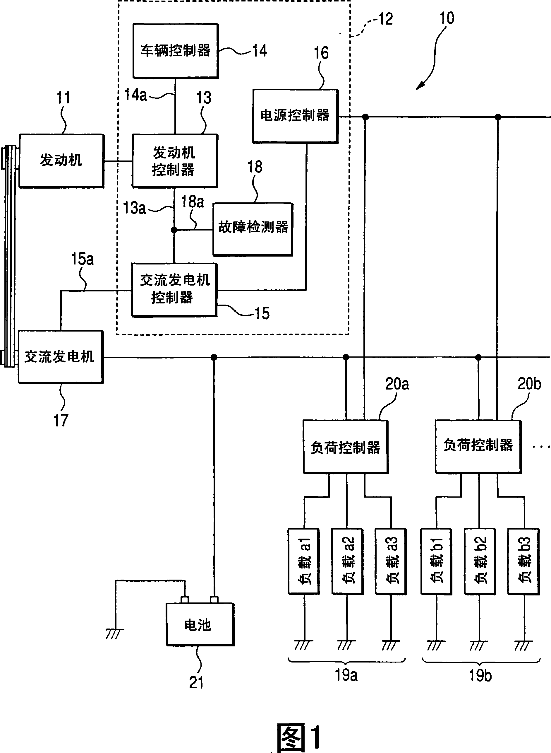
[0039] The overall structure of an engine control system according to a first embodiment of the present invention will be described in detail below with reference to FIG. 1 .

[0040] As shown in FIG. 1, the engine control system 10 is applied to a vehicle internal combustion engine 11, which includes various systems such as an air intake system, a fuel injection system, and an ignition system. The engine control system 10 includes a control device 12 for controlling the internal combustion engine 11 and an alternator 17 as auxiliary equipment.

[0041] The engine control device 12 includes an engine controller 13, which is connected with the air intake system, the fuel injection system, and the ignition system of the engine 11 for controlling these components according to the conditions of the vehicle. In addition to the engine controller 13, the engine control device 12 includes a vehicle controller 14, an alternator controller 15 as an auxiliary equipment controller, a powe...

no. 2 example

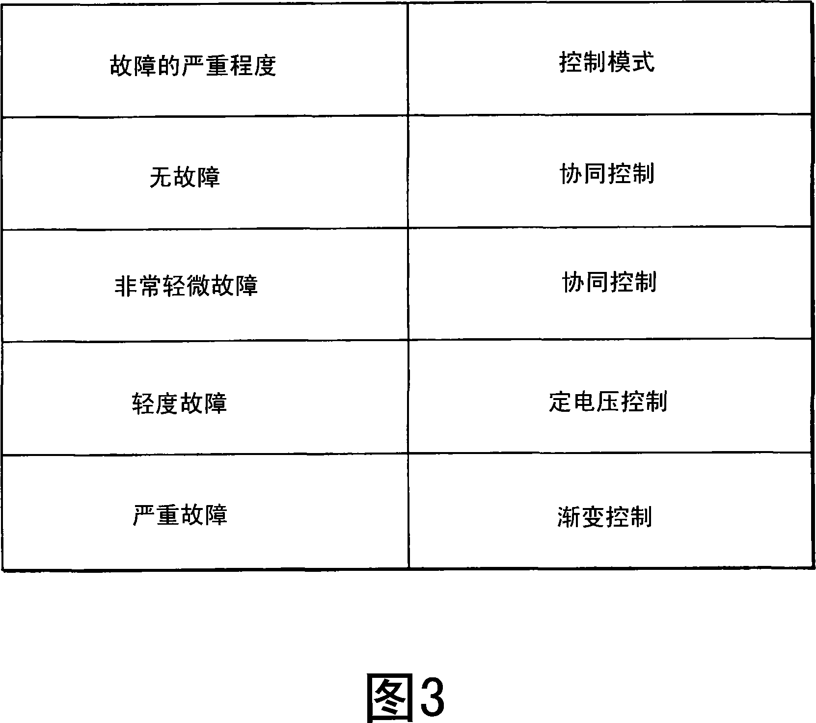
[0092] For the engine control system 10 of the above-mentioned first embodiment, the control mode is switched between the constant voltage control mode and the gradual change control mode according to the severity of the fault detected by the fault detector 18. According to the severity of the fault detected by the controller 18 and the engine operating condition, the control mode is switched between the constant voltage control mode and the gradual change control mode.

[0093] Next, an engine control system of a second embodiment to which the above concept is applied will be described with reference to FIG. 7, which shows an alternator control routine used in the second embodiment. Except for the alternator control program shown in FIG. 7, the engine control system of the second embodiment has the same structure as that of the control system of the first embodiment. Therefore, when introducing this embodiment, those of the first embodiment Components in the Engine Control Sy...


PUM


Abstract

An engine control method and related engine control method are disclosed for an engine with an auxiliary device of a vehicle wherein auxiliary device control means controls a drive torque of the auxiliary device, engine control means executes an engine torque control to vary the output torque of the engine, and failure detecting means detects a failure giving an adversely affect to engine torque control executed with the engine control means. The auxiliary device control means alters a drive control mode of the auxiliary device in response to the failure detected with the failure detecting means. In preferred embodiment, the auxiliary device is driven in a collaborative control mode in the presence of an extremely mild failure, a fixed voltage control mode in the presence of a mild failure and a gradual change control mode in the presence of a fatal failure.

Description

[0001] Cross References to Related Applications [0002] This application is related to Japanese Patent Application No. 2006-186245, which was filed on July 6, 2006, the contents of which are incorporated into this application as a background reference. technical field [0003] The present invention relates to a control system for an engine with auxiliary equipment, and more particularly, the present invention relates to a control system for use on an engine with auxiliary equipment that has an effect on the engine output torque ( hereinafter referred to as "engine torque") to control the driving torque of auxiliary equipment driven by the function. Background technique [0004] Modern vehicles are fitted with various engine-driven auxiliary equipment - such as alternators, air-conditioning compressors, power steering compressors, motor-generators, booster pumps to increase fuel pressure, and oil pumps. [0005] These auxiliary devices are driven by the torque of the engin...

Claims


Application Information

Patent Timeline
Patent Type & Authority Applications(China)
IPC IPC(8): F02D29/00F02D29/06F02D29/02F02D29/04H02P9/04
CPCF02D2250/24B60K25/00F02D41/021Y02T10/40F02D2200/1004F02D41/1497F02D41/221
Inventor 山下幸宏大林和良谷惠亮田中克典下山武志山本直树
Owner DENSO CORP
Why Eureka
Try Eureka