Diaphragm pump

A diaphragm pump and diaphragm technology, which is used in pumps, pumps with flexible working elements, and liquid variable-capacity machines, etc., can solve the problems of rapid and unstable airflow in and out, the motor directly bears a large load, and the structure of the intake valve is complex. To achieve the effect of good air outlet, low cost and simple mechanism

Active Publication Date: 2008-01-09
CHANGZHOU FULING & CEIEC
View PDF0 Cites 10 Cited by
  • Summary
  • Abstract
  • Description
  • Claims
  • Application Information

AI Technical Summary

Problems solved by technology

[0005] The air flow structure of the above-mentioned existing diaphragm pump is to inhale from top to bottom, and the air flow enters the air bag through the air intake valve and then is discharged through the air outlet valve. Because the space of the air bag is small, the air flow in and out is fast and unstable, and the noise is large; the umbrella shape The air intake valve has a complex structure, difficult manufacture, difficult assembly, and high cost; the connecting rod is rigidly fixed to the eccentric wheel, the motor directly bears a large load, and consumes a large amount of current

Method used


Image

  • Diaphragm pump
  • Diaphragm pump
  • Diaphragm pump

Examples


Embodiment Construction

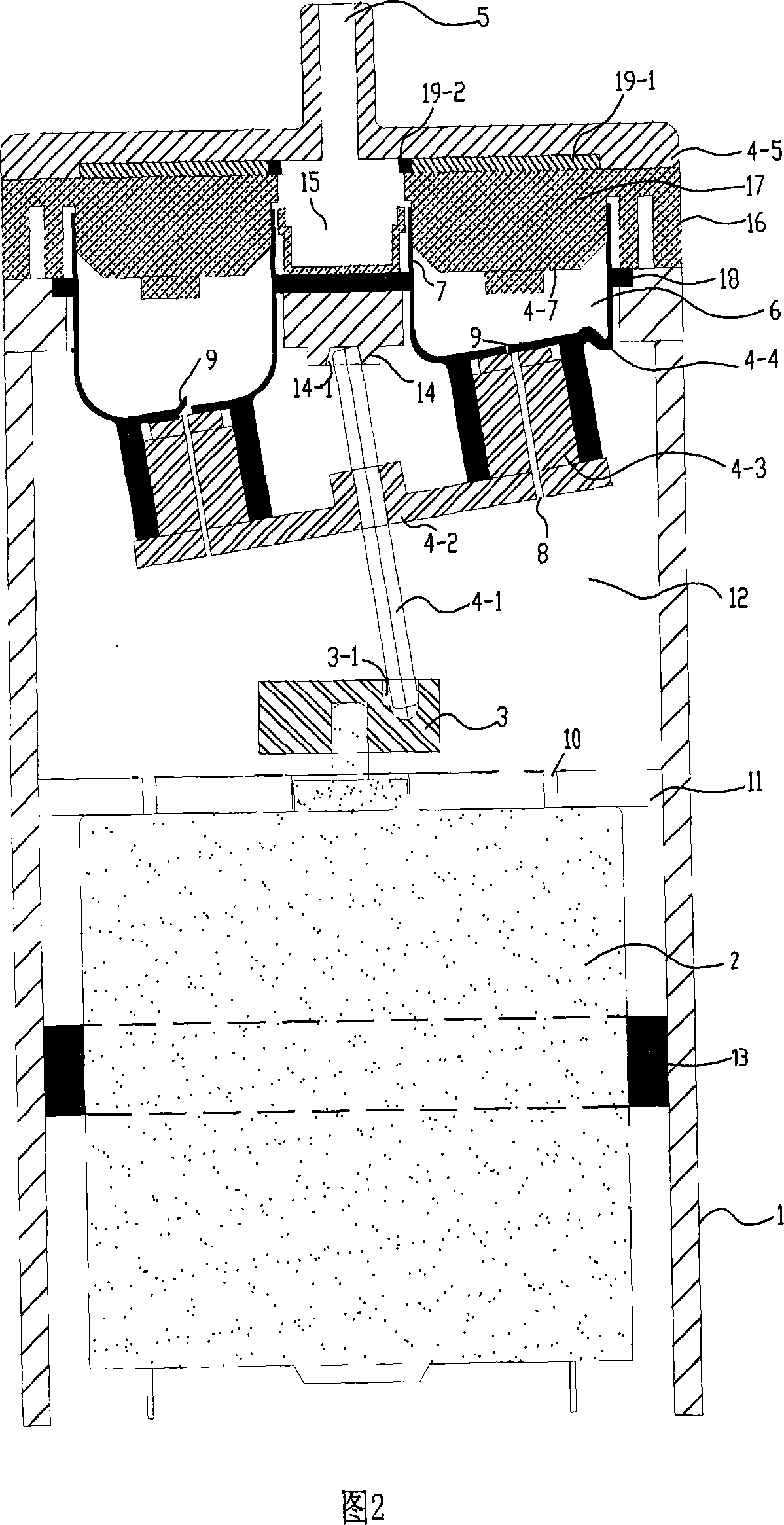
[0025] A diaphragm pump as shown in Figure 2 has a casing 1, a diaphragm pump assembly is arranged in the casing 1, and a motor 2 for driving the diaphragm pump assembly is arranged at the rear end; a rotating shaft is fixedly arranged on the output shaft of the motor 2 wheel 3; the diaphragm pump assembly includes a connecting rod 4-1 eccentrically connected to the runner 3, a rotating frame 4-2 fixedly connected to the connecting rod 4-1, and a driving part 4 arranged on the upper surface of the rotating frame 4-2 -3. The diaphragm part 4-4 connected with the driving part 4-3, and the air outlet cover 4-5 connected with the casing 1 and provided with the air outlet 5, the diaphragm pump assembly also includes the diaphragm part 4-4 The upper boss 4-7, the diaphragm part 4-4 is a cylindrical structure with one end open, and the open end is elastically wrapped on the outer circumferential surface of the boss 4-7 to form a pump chamber 6 inside the diaphragm part 4-4 , a cylind...


PUM


Abstract

This invention relates to gas variable displacement mechanical field, especially a diaphragm pump. It has machine case, in which is arranged with diaphragm pump components. The back side of machine case is set with electric engine which drives diaphragm pump components. Boss, diaphragm part and driving part form a gas absorbing and exhausting function element. At the interior of machine case, the air flow passes air inlet opening, semicircular air inlet valve, pump chamber, barrel type air outlet valve and air outlet opening in turn. This invention reduces energy consumption and working noise.

Description

technical field [0001] The invention relates to the field of gas variable capacity machinery, in particular to a diaphragm pump. Background technique [0002] The existing diaphragm pump has a structure as shown in FIG. 1 . In this figure, 21 is a motor, 22 is an output shaft of the motor 21, 23 is an eccentric wheel fixed on the output shaft 22, 24 is a drive shaft obliquely fixed on the eccentric wheel 23, and 26 is a drive shaft that can be fixed relative to the drive shaft 24. 27 is a casing, 28 is a cylinder part, and 29 is a valve cover of the drive body mounted for rotation. 31 is a diaphragm part, 32 is a cylindrical discharge valve, and this diaphragm part 31 and discharge valve 32 are integrally formed and comprise the diaphragm main body 30. The diaphragm main body 30 is fixed by the cylinder portion 28 and the valve cover 29 . In addition, 33 and 34 are the valve chamber part (common room) integrated with the valve cover 29, and a discharge port, 35 is a sucti...

Claims


Application Information

Patent Timeline
Patent Type & Authority Applications(China)
IPC IPC(8): F04B45/047
CPCF04B43/04F04B43/028F04B43/025F04B45/047
Inventor 蒋磊杰刘鸿博
Owner CHANGZHOU FULING & CEIEC
Why Eureka
Try Eureka