Centrifugal pump mouth ring sealing device

A ring seal and pump port technology, applied in the field of centrifugal pump port ring seal structure, can solve the problems of limited application range, short service life, large radial size, etc., and achieve long service life, small overall radial size, and reliable sex enhancing effect

Active Publication Date: 2008-01-09
西安航天泵业有限公司
View PDF0 Cites 5 Cited by
  • Summary
  • Abstract
  • Description
  • Claims
  • Application Information

AI Technical Summary

Problems solved by technology

[0003] The purpose of the present invention is to propose a centrifugal pump mouth ring sealing device, which solves the technical pr

Method used


Image

  • Centrifugal pump mouth ring sealing device
  • Centrifugal pump mouth ring sealing device

Examples


Embodiment Construction

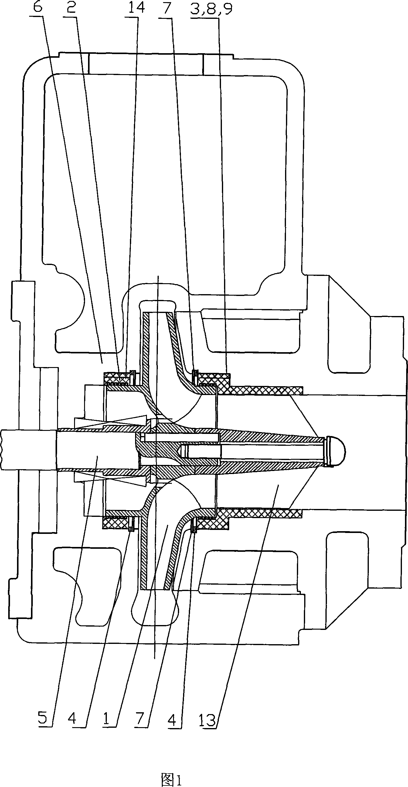
[0018] The structure of the first sealing device of the present invention is shown in Figure 1. It includes the impeller 1, the sealing ring 2, the retaining ring 4, the retaining ring groove 7, and the fastening device; the retaining ring groove 7 is arranged on the inner side of the pump housing 6, and the retaining ring 4 It is arranged in the retaining ring groove 7 to prevent the sealing ring 2 from loosening in the axial direction; the fastening device is arranged between the pump casing and the impeller to fix the sealing ring in the direction of rotation. It includes a fixed key 3 and an axial arrangement The outer groove 8 on the inner side of the pump housing 6 and the inner groove 9 axially arranged on the outer side of the sealing ring 2, and the fixed key 3 is arranged between the outer groove 8 and the inner groove 9. The pump shaft 5 and the gearbox output shaft are one shaft. The gearbox obtains power from the outside through a coupling. After speed change, the pum...


PUM


Abstract

This invention relates to centrifugal pump ring sealing device. It includes sealing ring between pump case body and blade; fastening device fixing the sealing ring in rotating direction; closing ring; closing ring groove at internal face of pump case. The closing ring is arranged in the closing ring groove in order to prevent sealing ring moving in axial direction. The fastening device is composed of a fixing key, outer groove and inner groove. The outer groove is set at the internal face of pump case in axial direction. The inner groove is set at the external face of sealing ring in axial direction. The fixing key is set between outer and inner grooves. This invention has small size in radial direction. The sealing device is widely applied. It is convenient to assemble and repair. The service life is long.

Description

Technical field [0001] The invention relates to a sealing structure, in particular to a mouth ring sealing structure for a centrifugal pump. Background technique [0002] Existing centrifugal pumps often have floating or fixed sealing devices arranged on the matching surfaces of the front and rear mouth rings of the impeller due to the need for sealing. The sealing ring of the floating sealing device is generally made of non-metallic material, but the installation structure is more complicated, the radial size is large, and the reliability is not high; the sealing ring of the fixed sealing device is generally made of soft metal material, which is fastened to the pump casing with screws Due to the different metal materials, this structure has great differences in physical properties and poor reliability. Once it rubs against the rotating part, it is easy to damage the rotating part and the sealing device itself. In order to prevent large damage caused by friction, the sealing ring...

Claims


Application Information

Patent Timeline
IPC IPC(8): F04D29/16
Inventor 赵卫忠韩卫钊朱保民曾伟杨延广赵凯吕秋洁刘爽马玉琴席建厂杨沛
Owner 西安航天泵业有限公司
Why Eureka
Try Eureka