
Embossing device with a deflection compensated roller

A technology of rollers and embossing rollers, which is applied in the direction of shafts and bearings, machining/deformation, etc., can solve the problem that the substrate cannot be compressed, and achieve the effect of reducing displacement

Inactive Publication Date: 2008-01-09
AVANTONE OY
View PDF4 Cites 7 Cited by
  • Summary
  • Abstract
  • Description
  • Claims
  • Application Information

AI Technical Summary

Problems solved by technology

The substrate in the roll end region may become incompressible

Method used


Image

  • Embossing device with a deflection compensated roller
  • Embossing device with a deflection compensated roller
  • Embossing device with a deflection compensated roller

Examples


no. 1 example

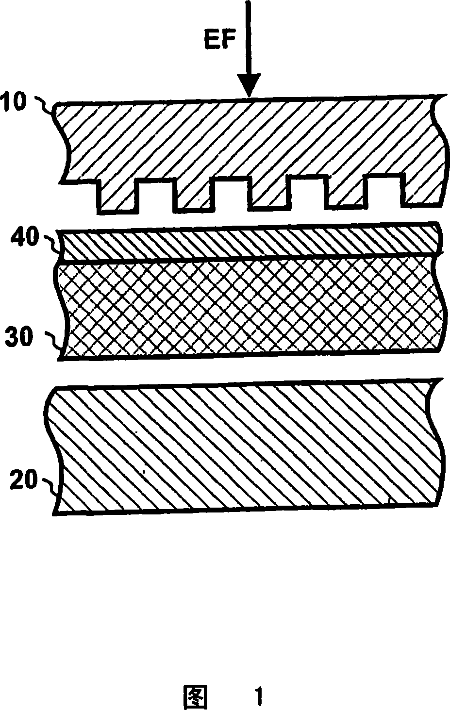
[0027] With reference to Fig. 1, microstructure is produced on the surface layer 40 of the substrate 30 by extruding the substrate positioned between the embossing roll 10 and the back-up roll 20, thereby forming a microstructure on the surface layer 40 of the substrate 30 and the embossing roll 10 The corresponding shape of the unevenness of the surface. For example, substrate 30 may be paper, cardboard or plastic. The skin layer 40 of the substrate 30 may be composed of a thermoplastic material, such as polyvinyl chloride, whose viscosity decreases at elevated temperatures. Some examples of suitable surface materials are listed in US Patent No. 4,913,858. Diffractive microstructures may have eg rectangular, symmetrical triangular, asymmetric triangular or sinusoidal shaped profiles.

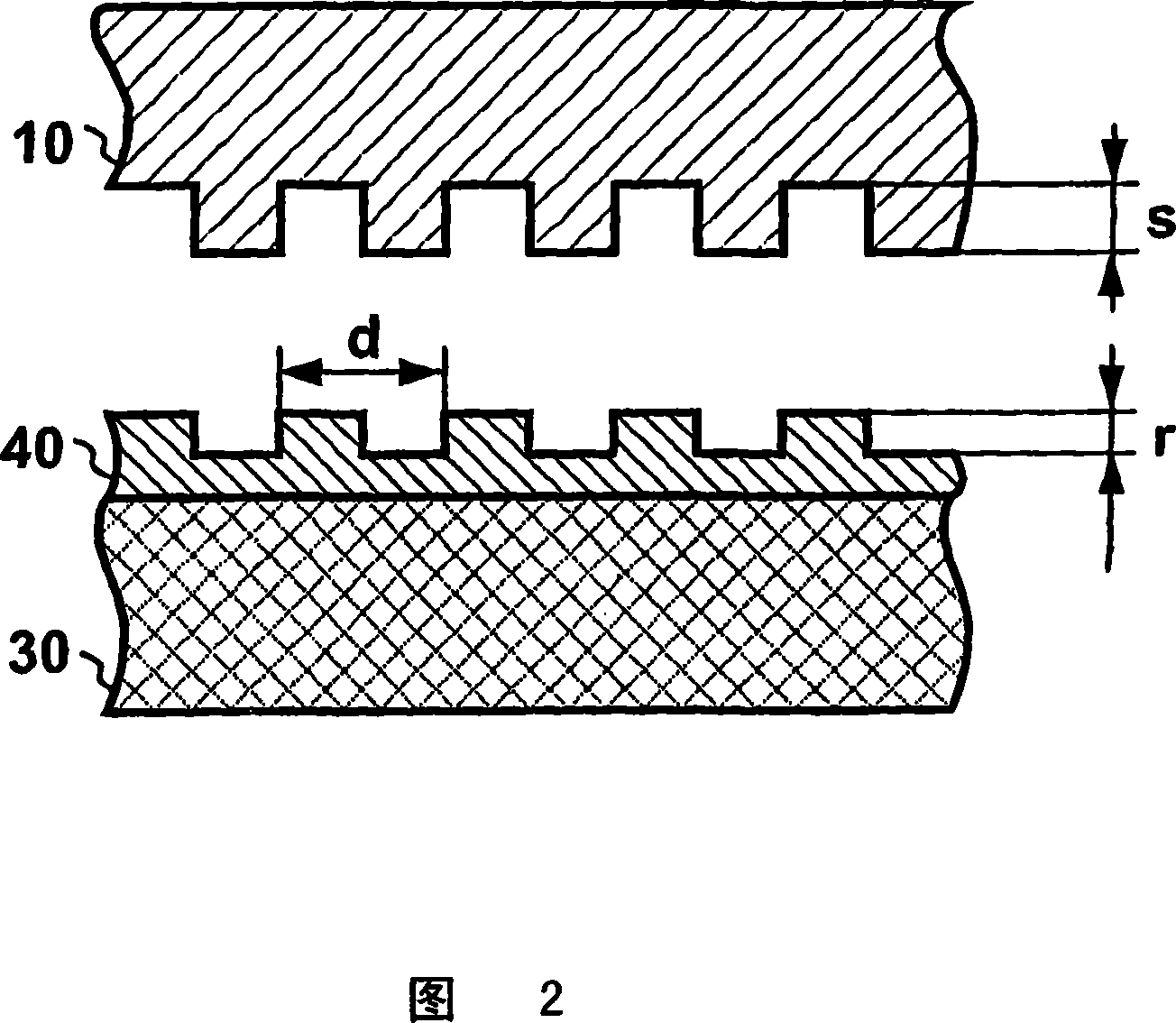
[0028] Referring to FIG. 2 , the shape of the diffractive microstructure embossed on the surface layer 40 of the substrate 30 corresponds to the surface structure of the embossing roll 10 . ...


PUM


Abstract

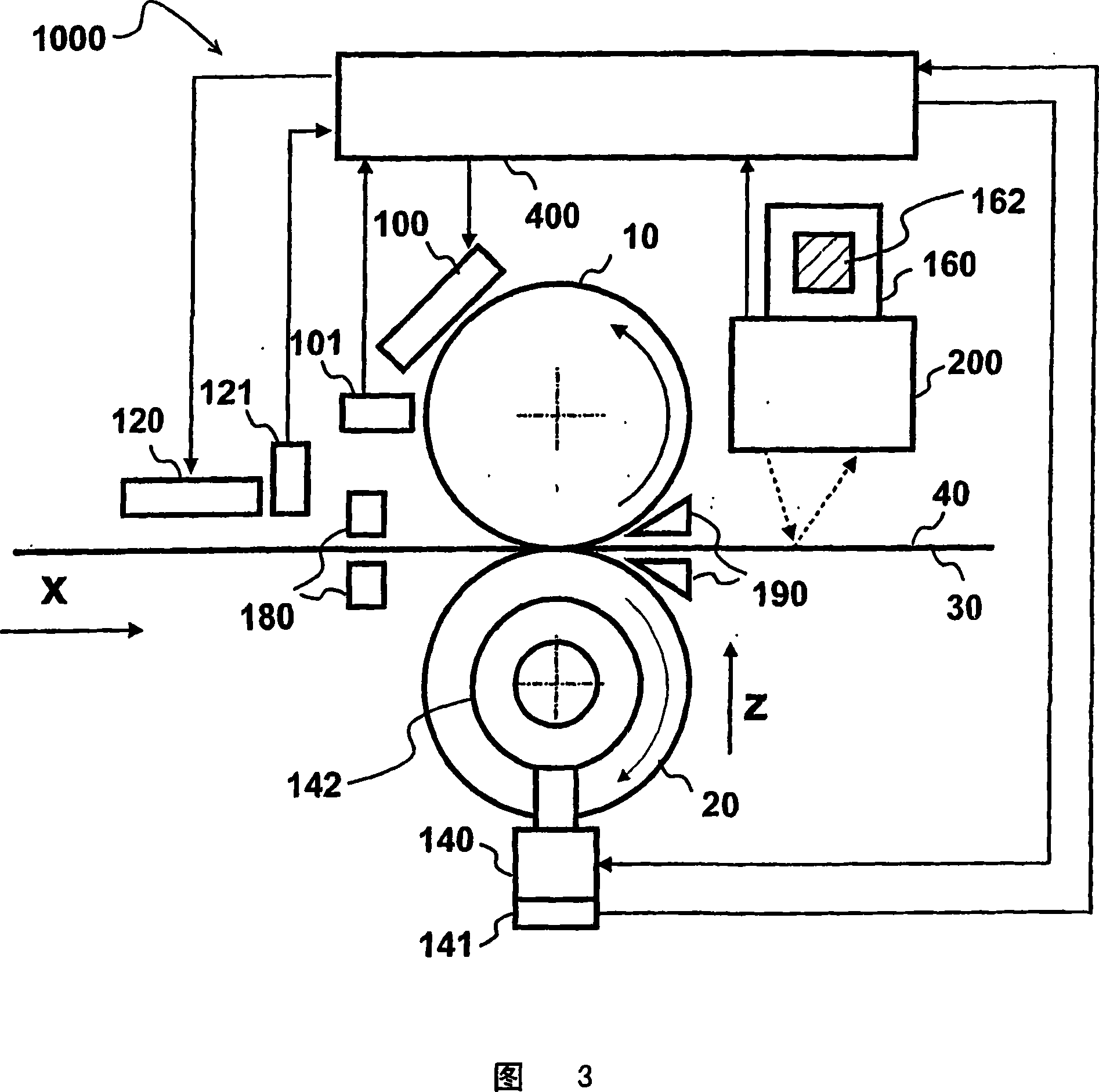
A diffractive microstructure is produced on the surface layer (40) of a substrate (30) using an embossing device (1000) according to the invention. The embossing device (1000) comprises an embossing roll (10) and a backing roll (20) for exerting an embossing pressure on the surface layer (40) of the substrate (30). The embossing pressure and / or variations in temperature cause deflection of the embossing roll (10). In order to compensate the deflection, the embossing device (1000) comprises means for setting the embossing pressure (p3) exerted by the central area (CR) of the embossing roll (10) on the surface layer (40) of the substrate (30) to be at least equal to or higher than the embossing pressure (p1, p2) exerted by the end areas (ER1, ER2) of the embossing roll (10) on the surface layer (40) of the substrate (30). In a preferred embodiment the shell (21) of the backing roll (20) is supported on the central zone (CR) of the shaft (22) of the backing roll such that the ends of the shell (22) can move in relation to the shaft (22) of the backing roll. Thus, when the side of the shell (11) of the embossing roll on the substrate (30) side is bent due to the embossing pressure and becomes concave, the side of the backing roll on the substrate side becomes convex in a corresponding manner. Thus, the pressure in the central area (CR) becomes equal to or higher than in the end areas (ER1, ER2).

Description

technical field [0001] The invention relates to a method and a device for generating diffractive microstructures on the surface of a base sheet through embossing technology, wherein the device includes an embossing roller and a supporting roller to apply embossing pressure on the surface of the base sheet. Background technique [0002] Diffractive microstructures may create a visual effect on a product or be used to identify a product. [0003] For example, diffractive microstructures can be produced by embossing the surface of a substrate coated with a suitable lacquer. During embossing, the lacquered substrate is pressed between an embossing member and a pressure-bearing member, wherein the surface of the embossing roll comprises a relief corresponding to the microstructure. For example, the embossing part and the pressure part are rotating drums. During the embossing process, the support roller supports the substrate from the back, so that sufficient pressure, ie emboss...

Claims


Application Information

Patent Timeline
Patent Type & Authority Applications(China)
IPC IPC(8): F16C13/00B31F1/07B81CF16C
CPCF16C13/024B31F1/07B31F2201/0753
Inventor R·科霍南P·科伊武库纳斯
Owner AVANTONE OY
Learn More