Radio frequency identification tag security systems

A radio frequency identification system and label technology, applied in the field of RFID technology, can solve problems such as recoding

Active Publication Date: 2008-01-09
BRITISH TELECOMM PLC
View PDF1 Cites 9 Cited by
  • Summary
  • Abstract
  • Description
  • Claims
  • Application Information

AI Technical Summary

Problems solved by technology

The disadvantage of this method is the cost and management of using the infrastructure
Each time ownership or control of a tagged item changes hands, parties in the supply chain must have the necessary eq

Method used


Image

  • Radio frequency identification tag security systems
  • Radio frequency identification tag security systems
  • Radio frequency identification tag security systems

Examples


Embodiment Construction

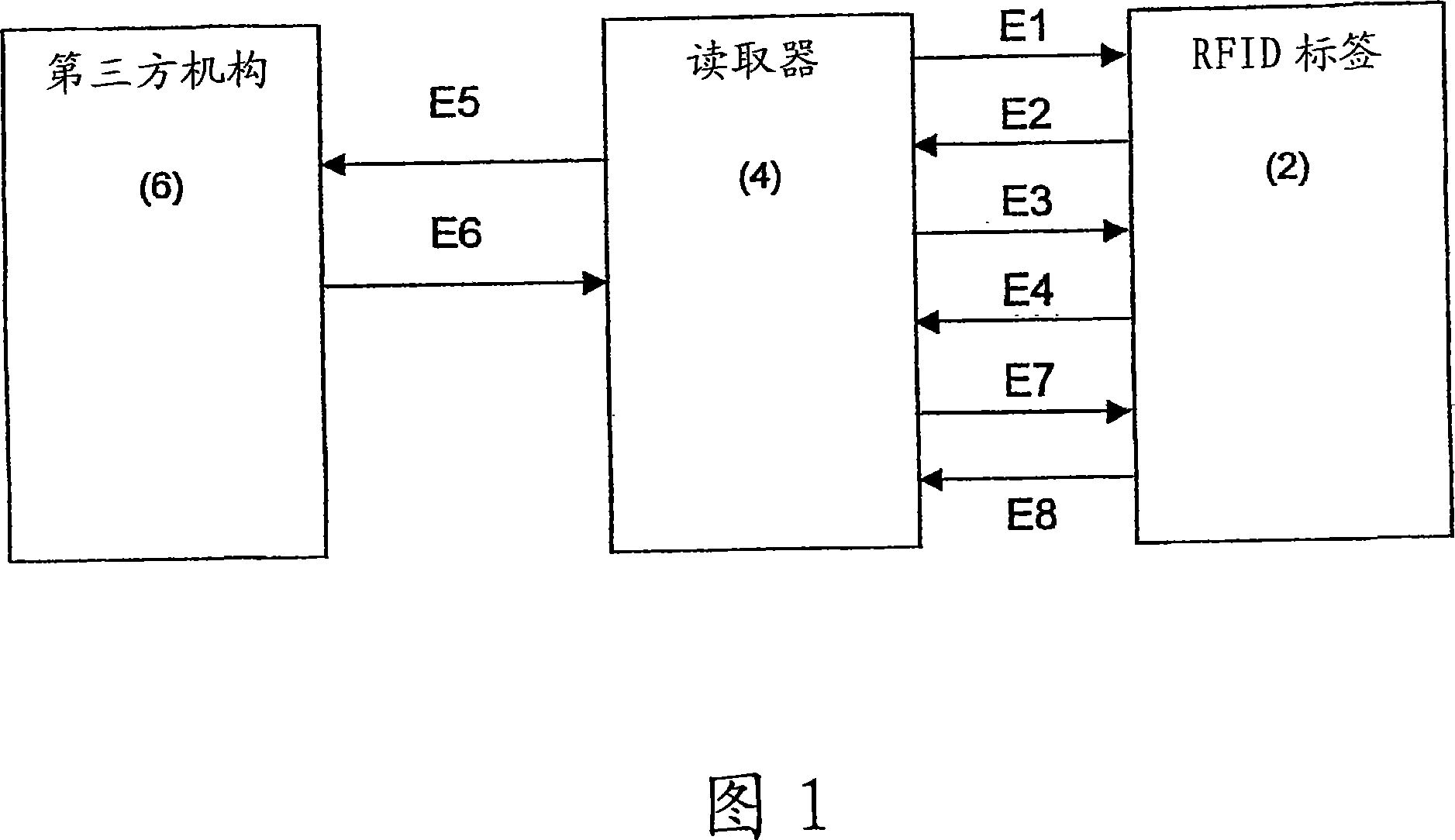
[0043] Fig. 1 is a schematic overview of an embodiment of the present invention, showing the relationship and communication between the three main components of the RFID system according to the present invention. Multiple exchanges E1 to E5 occurred during the event between the tag, the reader and the third party agency.

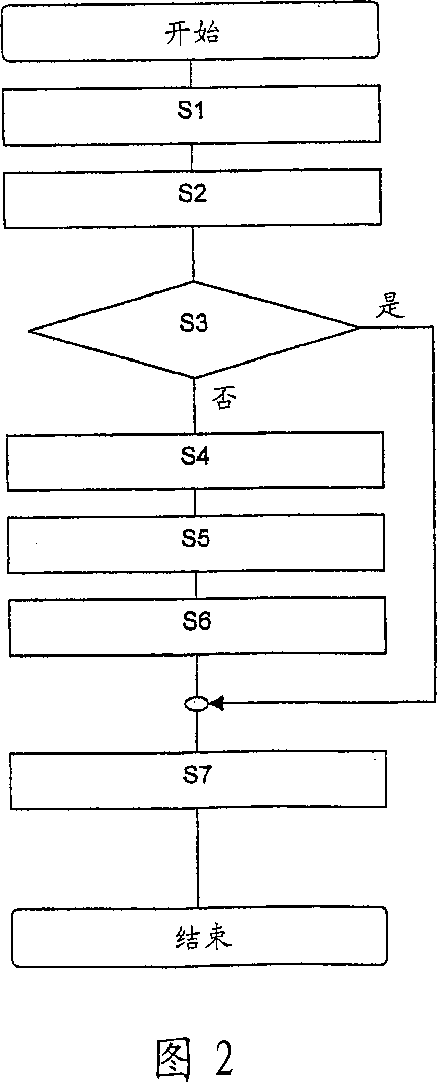
[0044] Figure 2 is a flowchart describing the steps of a typical read and access session.

[0045] The embodiment of the present invention will now be discussed in conjunction with FIG. 1 and FIG. 2.

[0046] In step S1 of Figure 2, the reader (4) establishes initial contact with the tag (2) by scanning the tag (2) with appropriate radio frequency radiation. This is depicted by the arrow labeled E1 in Figure 1.

[0047] In step S2, the tag responds by sending an output E2 including the "pseudo name" to the reader.

[0048] In step S3, the reader receives the pseudo-name (output E2). If the reader has information in itself that allows it to "decode" the pseudonym...


PUM


Abstract

Security and privacy of tag information in an RFID-based system can be achieved through the usage of pseudonyms generated based on one-way hash functions. A system based on binary one-way trees allows for the scalable generation and decoding of authentication keys to obtain access to tag identities. The apparatus and methods described can also be adapted to provide limited access for readers to tag information.

Description

Technical field [0001] The present invention generally relates to RFID (Radio Frequency Identification) technology, and specifically, describes an apparatus and method for operating a security system and a privacy system using this technology. Background technique [0002] Radio Frequency Identification (RFID) is a technology with high potential that can fundamentally change the way information related to the physical world is collected. RFID tags are usually used to identify multiple items without sight or manual intervention. Using RFID, cargo containers (pallets) in the supply chain can be counted without unloading or unpacking the containers. By allowing checkout without queuing and suppressing counterfeiting, RFID embedded in consumer products can provide customers with a new shopping experience. After the initial point of sale, RFID tags can be used by consumers to implement services in their homes, or used for product returns, recycling, and second-hand sales. Automatic id...

Claims


Application Information

Patent Timeline
IPC IPC(8): G06K17/00G06K7/00G06F21/31G06F21/44G06F21/62G06F21/73
CPCG06K17/0022H04L9/32G06F21/73H04L2209/42H04L9/0836H04L2209/805G06F21/445G06K7/0008H04L2209/30G06K7/10049G06F2221/2129G06F2221/2115H04L9/3273G06F21/6209G06F21/31H04L9/321G06K17/00G06K7/00
Inventor 特雷弗·伯布里奇安德列·亚索伯拉
Owner BRITISH TELECOMM PLC
Why Eureka
Try Eureka