Joint parts numerically controlled process clamping method and milling tool

A part and clamping technology, which is applied to the CNC machining and clamping method of the main support joint of the aircraft and the field of milling tools, can solve the problems of not opening the processing groove, the milling tool is difficult to design, and is not practical, so as to improve the CNC machining efficiency. , easy to position and fix, simple to design and manufacture

Active Publication Date: 2008-01-16
XIAN AIRCRAFT BRANCH OF XIAN AIRCRAFT INT
View PDF0 Cites 12 Cited by
  • Summary
  • Abstract
  • Description
  • Claims
  • Application Information

AI Technical Summary

Problems solved by technology

[0003] Usually, the method of processing joint parts is to use vacuum milling tools and use the web surface of the joint for positioning. As the structure of joint parts becomes more and more complex, the processing grooves have become closed, and the web surfaces are rela

Method used


Image

  • Joint parts numerically controlled process clamping method and milling tool
  • Joint parts numerically controlled process clamping method and milling tool

Examples


Embodiment Construction

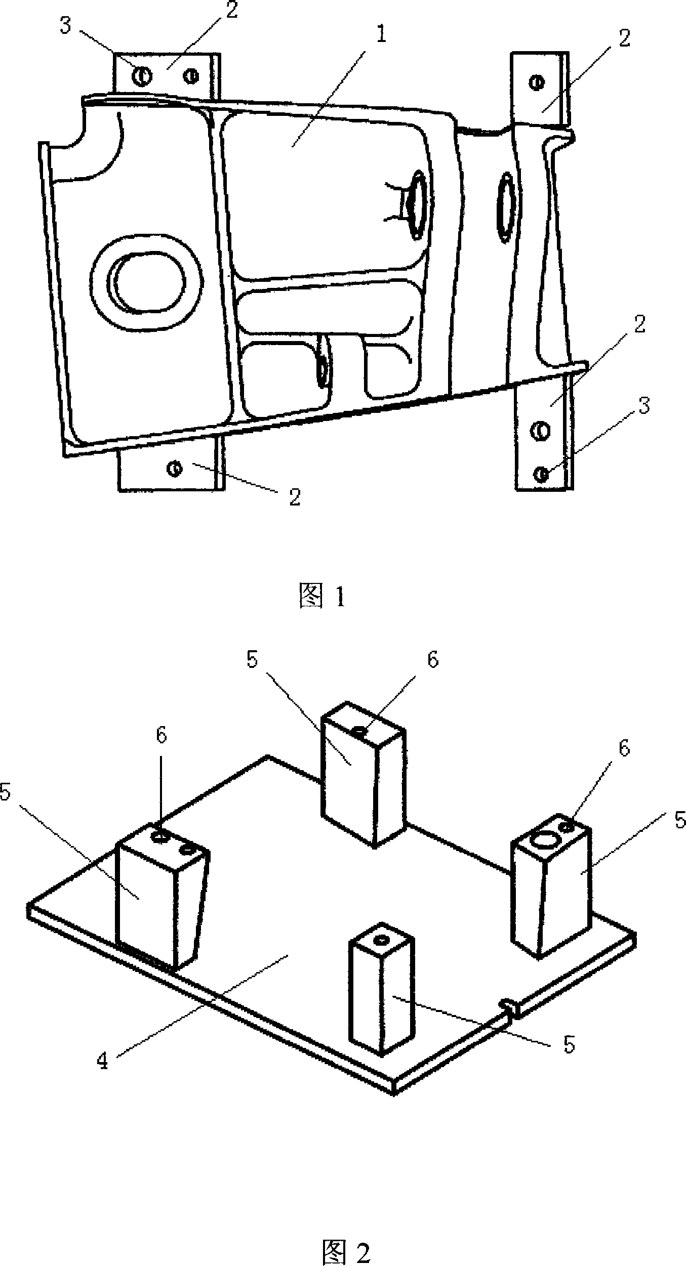
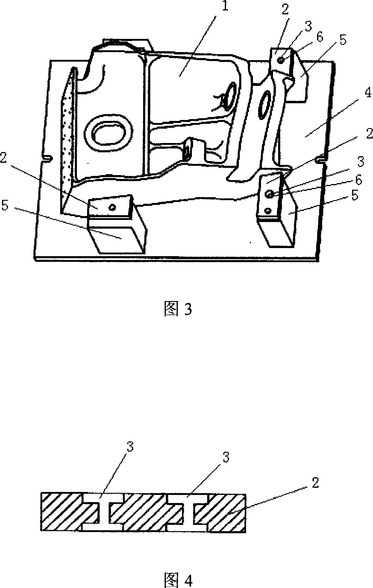
[0014] The joint part 1 shown in FIG. 1 is a complex box-shaped structure, and four process positioning tables 2 are arranged on the theoretical shape of both sides of the part (the process positioning tables are removed after the part is processed). Each process positioning table is provided with a connection positioning hole 3. In practice, the connection positioning hole 3 is an inner hexagonal bolt hole, as shown in FIG. 4, so that the connection bolt is not higher than the surface of the process positioning table. The milling tool of FIG. 2 includes a milling body 4 and four support blocks 5. The milling body 4 is a stable plate-like structure, and the support block 5 is a columnar structure with a support surface. The support blocks are respectively fixed on the periphery of the milling body’s flat plate structure. Position, the connection between the support block and the milling unit is fixed by socket head cap screws and open washers. The support surface of the support...


PUM


Abstract

The invention provides a digital control processing fixture method of parts like complicated joints and a design of a clamp. The main idea is that the joint part is fixtured in suspension. The fixture method is that process positioning stations are arranged on the theoretical shapes of two sides of the part; supporting blocks, which correspond to the process positioning stations and are higher than a milling tool, are arranged on the milling tool; the process positioning stations on the two sides of the part are positioned and fixed on the supporting blocks of the milling tool to make the joint part fixtured in suspension on the milling tool.

Description

technical field [0001] The invention relates to aviation manufacturing technology, directly relates to a clamping and milling tool design method in the numerical control machining of joint parts, and in particular relates to a numerical control machining clamping method and a milling tool for various aircraft main lifter support joints. Background technique [0002] At present, with the rapid development of CNC machining technology and aircraft design technology, many parts assembled together on the aircraft are gradually designed into integrated single parts. These single parts are more and more complex in structure and larger in volume. As the largest and most complex joint on the aircraft, the main lift support joint is an important force member connecting the wing and the main landing gear. It needs to meet the load strength requirements of the aircraft's take-off and landing, and ensure the coordination of the assembly of the landing gear and the wing. The material is a...

Claims


Application Information

Patent Timeline
IPC IPC(8): B23Q3/00
Inventor 史靠军周文东段学峰吴峰
Owner XIAN AIRCRAFT BRANCH OF XIAN AIRCRAFT INT
Why Eureka
Try Eureka