LED road lamp and its lens

A LED street lamp and lens technology, applied in the field of LED lighting, can solve problems such as uneven brightness and darkness, low illumination, and poor uniformity, and achieve the effects of clear edges, uniform illumination, and reduced light loss

Inactive Publication Date: 2008-01-16
SHENZHEN BANG BELL ELECTRONICS
View PDF0 Cites 78 Cited by
  • Summary
  • Abstract
  • Description
  • Claims
  • Application Information

AI Technical Summary

Problems solved by technology

[0003] LED street lights usually cover the LED with a lens to collect light, but the existing lens projects a circular light spot, and the light intensity difference between the center and the periphery is large; in addition, for some In occasions where a large range of lighting is required but a small range of lighting is required in another direction, such as road lighting, a wide range of illumination is required in the direction of the road extension, good lighting effects, and a large angle requirement; while in the direction perpendicular to the road, it is not necessary to have a wide range of lighting. range of lighting, otherwise, it will not only waste electricity, but also cause light pollution to the surrounding environment
However, for the existing circular lens LEDs, the light intensity requirements can only be achieved by installing more lamps in the direction of the road extension and superimposing the light spots of adjacent lamps. Even so, it is difficult to avoid the lighting of the "rib road" As a result, the illuminance directly under the lamp is high, and the illuminance in other areas is low, resulting in low average illuminance and poor uniformity of the road surface. This uneven lighting directly affects driving safety.

Method used


Image

  • LED road lamp and its lens
  • LED road lamp and its lens
  • LED road lamp and its lens

Examples


Embodiment Construction

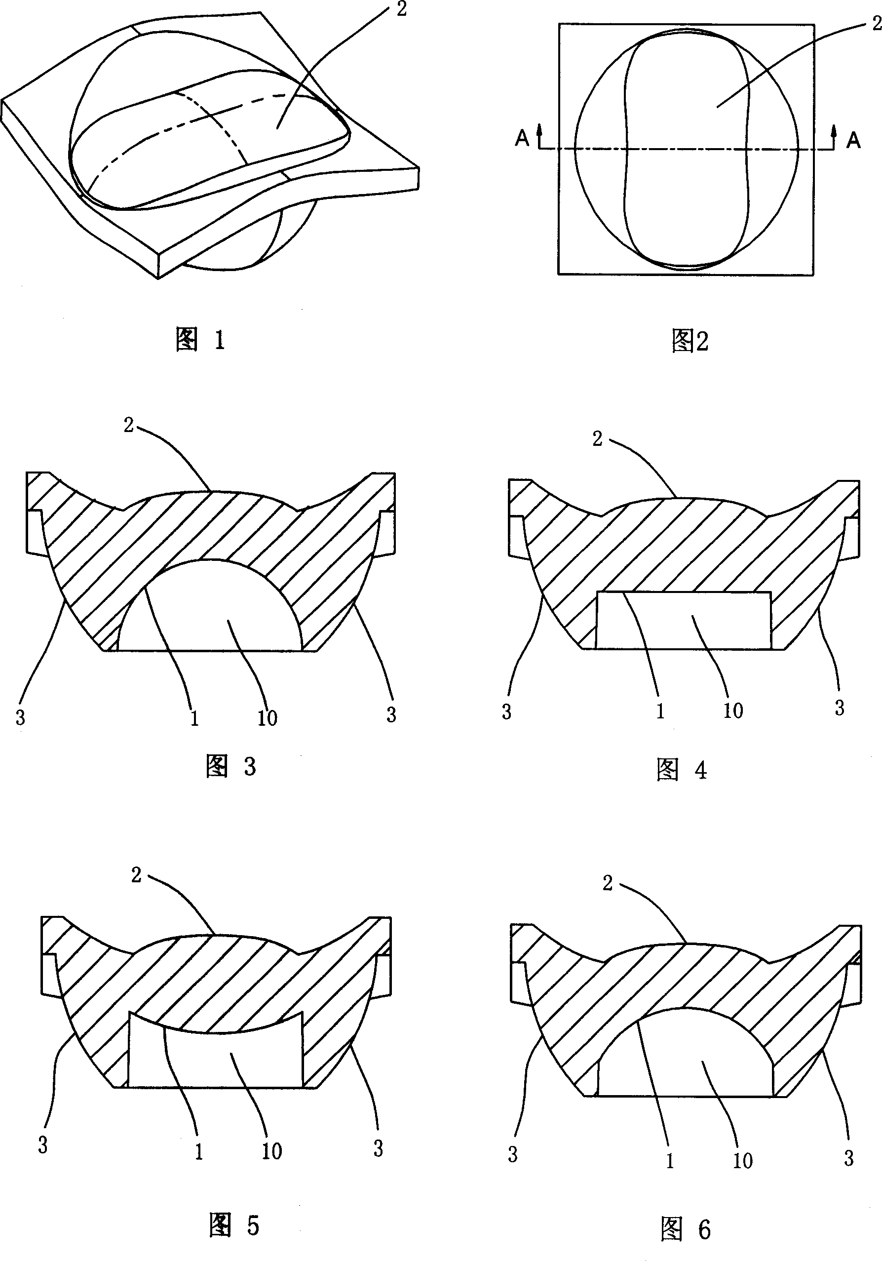
[0031] As shown in Fig. 1 to Fig. 3, the present invention provides a kind of lens that LED street lamp is used, and the middle part of the first side of described lens is provided with a pit 10, can be used for a LED to be installed in the circle center of pit 10, pit 10 The wall surface of the pit constitutes the incident surface 1 of the lens; the middle part of the second side of the lens protrudes in an arc shape to form a pillow-shaped exit surface 2; the so-called pillow shape is generally in the shape of a long bar with both ends being arc surfaces, and The middle parts of both sides of the elongated body are slightly concave inwards, and the upper surface is convex, and the first side of the lens is provided with a circle of total reflection surface 3 around the concave hole 10 to reflect light to the exit surface 2 . The lens is preferably made of a transparent material with very good light transmission performance, such as PC or PMMA.

[0032] As shown in Figure 4, ...


PUM


Abstract

The invention relates to a lens for LED street lamp. A concave pit is provided in the middle of a first side face of the lens and allowing LED to be arranged therein, and the pit wall of the concave pit forms an incident face; an arcing bulge in the middle of a second side face of the lens forms an emergent face with the shape of pillow; and a totally reflecting face is circumferentially provided around the concave pit on the first side face of the lens. The invention also relates to a LED street lamp, which comprises a frame, and a lighting module arranged on the frame, wherein the lighting module comprises a thermal radiator, a substrate with a LED array, a PCB board with a through-hole array and a lens cap with a lens array. The substrate is provided on the undersurface of the thermal radiator, PCB board is provided on the outer surface of the substrate and connected with each LCD electrode, the lens cap is provided at the outer side of the PCB board, LEDs pass through the through-holes on the PCB board to be accommodated in the concave pit corresponding to the lens, and the lens array is formed by arranging and combining a plurality of above mentioned lenses. The invention can control the distribution of light to form rectangular light spot. The light in the effective illuminated zone is very uniform and there is no parasitic light outside the zone.

Description

technical field [0001] The invention relates to the field of LED lighting, in particular to an LED street lamp and a lens used therefor. Background technique [0002] Traditional municipal lighting fixtures mainly use sodium lamps, mercury lamps or metal halide lamps, but these lamps consume a lot of power, have a short lifespan, and have high maintenance costs, which are not conducive to environmental protection. Therefore, the use of LED lamps to replace traditional lamps has become a revolution in the field of lighting. [0003] LED street lights usually cover the LED with a lens to collect light, but the existing lens projects a circular light spot, and the light intensity difference between the center and the periphery is large; in addition, for some In occasions where a large range of lighting is required but a small range of lighting is required in another direction, such as road lighting, a wide range of illumination is required in the direction of the road extensio...

Claims


Application Information

Patent Timeline
Patent Type & Authority Applications(China)
IPC IPC(8): F21V5/04F21V17/04F21S2/00F21V29/00F21V19/00F21V31/00F21W131/103F21Y101/02F21K9/00F21V29/74F21Y115/10
CPCF21Y2101/02F21W2131/103Y02B20/72F21V5/04F21Y2115/10
Inventor 吴娟
Owner SHENZHEN BANG BELL ELECTRONICS
Why Eureka
Try Eureka