Synchromous machine drive system

A technology of synchronous motor and drive system, applied in control system, motor control, AC motor control and other directions, can solve problems such as risk of imbalance and inability to cope

Inactive Publication Date: 2008-01-16
PANASONIC CORP
View PDF1 Cites 2 Cited by
  • Summary
  • Abstract
  • Description
  • Claims
  • Application Information

AI Technical Summary

Problems solved by technology

However, since the value of ΔV is constant, it cannot cope with the acceleration and dec...

Method used


Image

  • Synchromous machine drive system
  • Synchromous machine drive system
  • Synchromous machine drive system

Examples


Embodiment Construction

[0007] Embodiments of the present invention will be described below using the drawings.

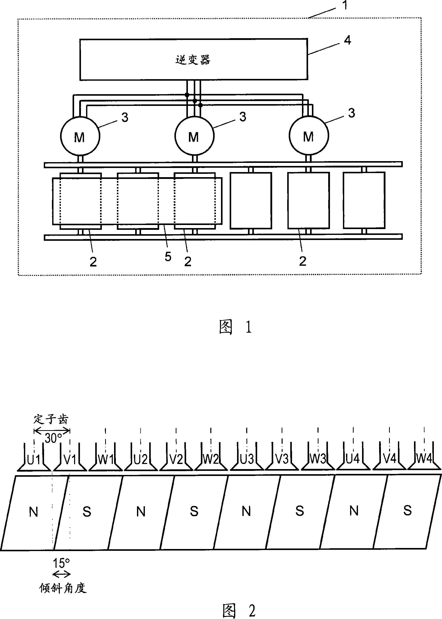
[0008] FIG. 1 shows a conveyance device 1 using a drive system according to an embodiment of the present invention.

[0009] The synchronous motor 3 drives the driving roller 2 , and the workpiece 5 loaded on the driving roller 2 is transferred by the rotation of the driving roller 2 . The inverter 4 synchronously drives the plurality of synchronous motors 3 .

[0010] FIG. 2 is a plan development view showing the structure of the synchronous motor 3 of the drive system according to the embodiment of the present invention, and is also an explanatory view of oblique magnetization of the magnet rotor. As shown in the figure, the synchronous motor 3 includes a stator core with 12 teeth and a rotor magnet magnetized by 8 poles. On the stator teeth, 3-phase 8-pole stator wires including U-phase, V-phase, and W-phase are wound in a concentrated winding method, and the rotor magnets are magnet...


PUM


Abstract

An inverter of in a synchronal motor drive system synchronally drives a plurality of synchronal motors containing the inclined magnet rotor after the magnetization. The inverter does a feedforward operation based on the inertia and the value of the acceleration-deceleration so as to automatically control the output voltage when the inverter drives the output frequency to change and operate in the acceleration-deceleration state.

Description

technical field [0001] The invention relates to a driving system for synchronously driving a plurality of synchronous motors. Background technique [0002] Recently, the use of synchronous motors excellent in controllability and efficiency has been increasing as drive motors for various devices. Furthermore, improvements to inverters for driving synchronous motors are also being proposed. When driving a synchronous motor, it is very important to prevent misalignment during acceleration and deceleration. For example, Japanese Patent Application Laid-Open No. 2005-143178 discloses a driving method for a hybrid synchronous motor in which ΔV is added to the output voltage of the inverter to prevent imbalance during acceleration and deceleration. However, since the value of ΔV is constant, it cannot cope with changes in acceleration and deceleration values ​​or load inertia (inertia), and there is a risk of loss of adjustment. Contents of the invention [0003] The synchrono...

Claims


Application Information

Patent Timeline
IPC IPC(8): H02P6/00H02P5/00
CPCH02P5/46H02P5/74H02P25/024H02P27/06H02P2207/05
Inventor 岩井龙一郎渡边聪松嵜景孝
Owner PANASONIC CORP
Why Eureka
Try Eureka