Air-float filter pool

An air flotation filter and air flotation technology, applied in the direction of filtration separation, filtration circuit, separation method, etc., can solve the problems of uneven water distribution, manual cleaning, and the depth of the air flotation pool, so as to improve the effective filtration area and simplify the Production management process, optimize the effect of water purification process

Active Publication Date: 2008-01-23
SHANGHAI MUNICIPAL ENG DESIGN INST GRP
View PDF0 Cites 4 Cited by
  • Summary
  • Abstract
  • Description
  • Claims
  • Application Information

AI Technical Summary

Problems solved by technology

[0003] 1. The depth of the air flotation pool is shallow, and it is difficult to connect with the elevation of the subsequent treatment structures
[0004] 2. The air flotation tank uses perforated water collection pipes to collect water unevenly, which affects the water quality of the effluent and the improvement of water production.
[0005] 3. During the long-term operation of the air flotation tank, mud will accumulate at the bottom of the tank or even block the perforated pipe, which requires regular manual cleaning
Although this kind of superimposition will not disturb the scum layer and affect the slag discharge of the air flotation tank like the moving cover filter when it is running, the layout of the central drainage tank or sand washing drainage tank will cause uneven water distribution on the upper and lower sides

Method used


Image

  • Air-float filter pool
  • Air-float filter pool
  • Air-float filter pool

Examples


Embodiment Construction

[0018] The present invention will be described in detail below in conjunction with the accompanying drawings and embodiments.

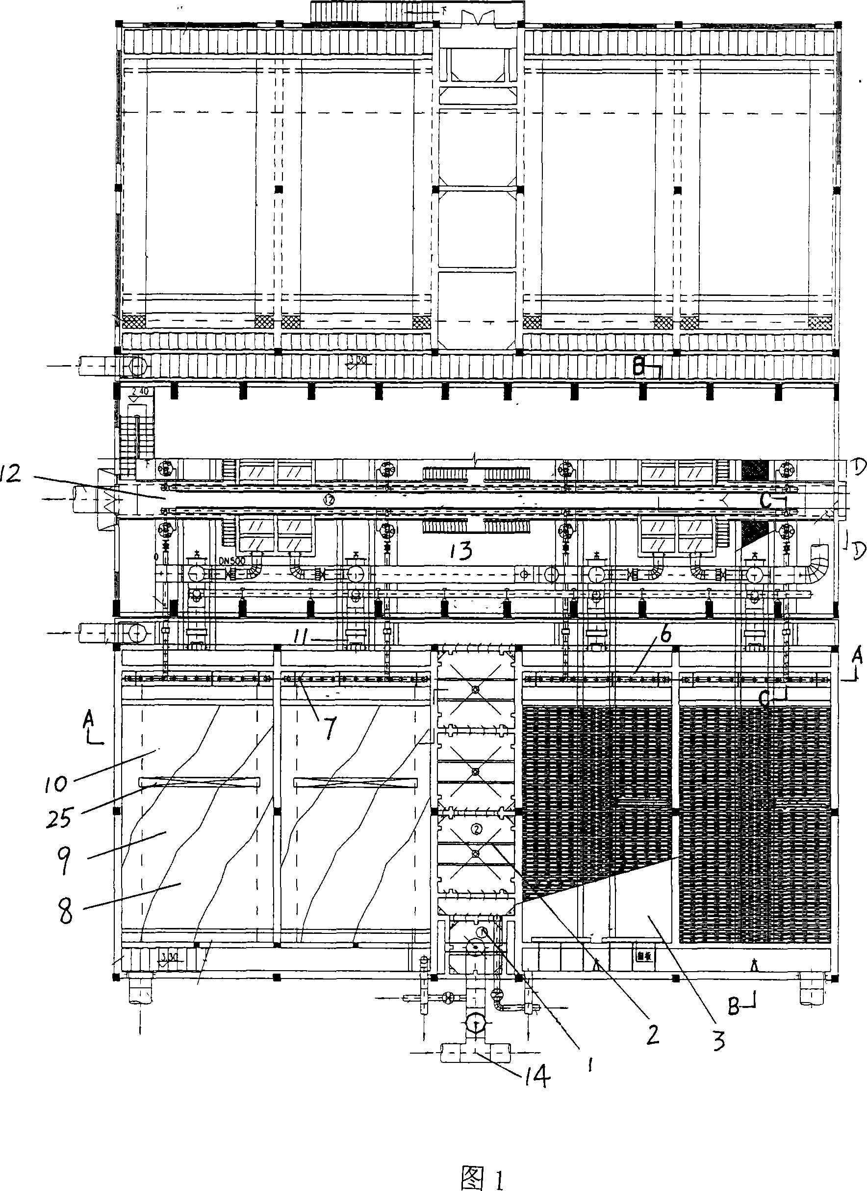
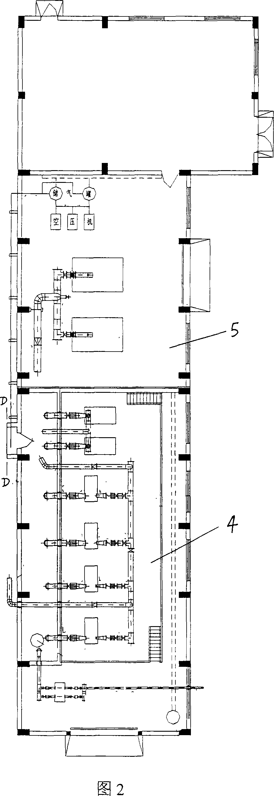
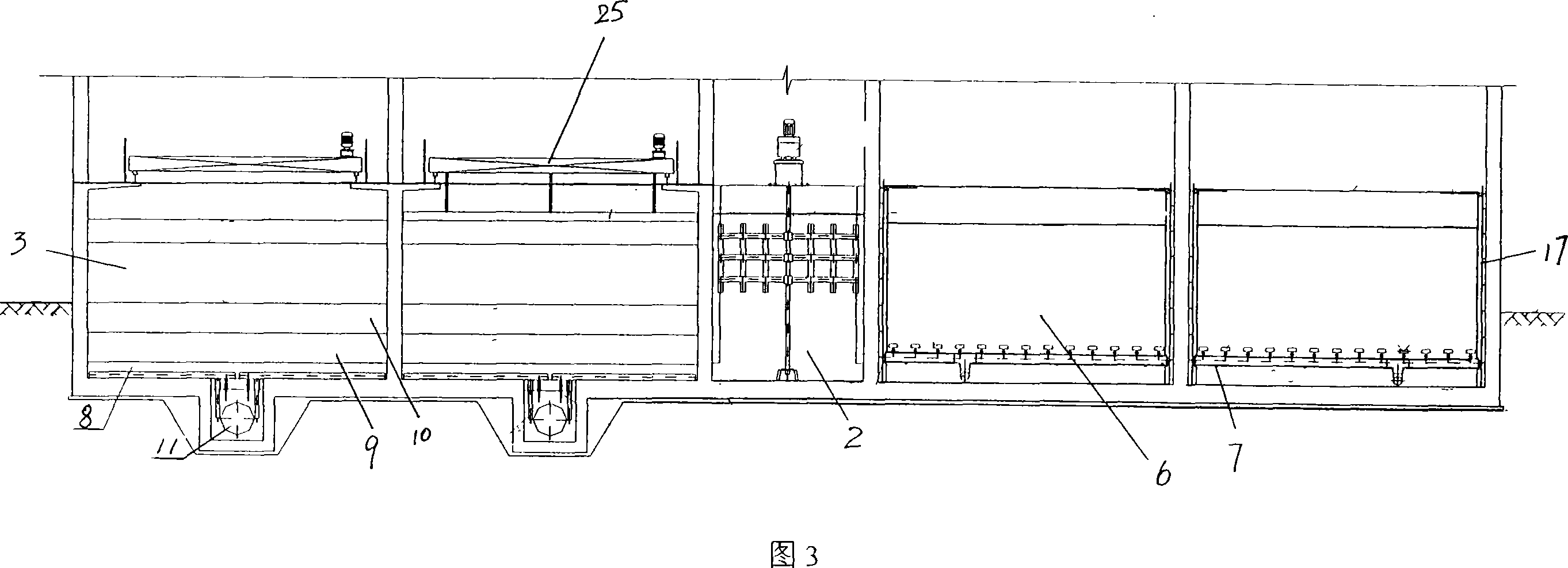
[0019] The embodiment shown in the figure is a design scale of 120,000 m 3 The / d air flotation filter has a total of 8 grid flap filter tanks 3, arranged in double rows, with 4 grids in each row. A mechanical mixing tank 1 and a group of mechanical flocculation tanks 2 are arranged in the middle of each row of filters, and a comprehensive pump room 4 and blower room 5 are arranged on the side of the flap filter 3. The single filter area of ​​the flap filter 3 is 100m 2 , 12.5m long and 8m wide. The filtered water is used as air flotation dissolved air water, and the reflux ratio is adjustable within the range of 5% to 10%. The design ascending velocity of the air flotation tank is 2mm / s, and the design filtration velocity of the filter is 7.2m / h. Figure 2 and Figure 1 are connected at the D-D line.

[0020] The air flotation filter is superimpose...


PUM

PropertyMeasurementUnit
particle diameteraaaaaaaaaa

Abstract

The invention relates to a floatation filtering pool, which is characterized in that: a solution gas discharge device is arranged in an turnover filtering pool, which is communicated with a solution gas cylinder by a pipeline. The flocculation poor is communicated with the front end of the turnover filtering pool by a water inflow main ditch , a floatation contact zone is arranged at the front part of the turnover filtering pool, the entrance of the floatation contact zone is arranged at the bottom of the front end of the floatation contact zone, the exit of the floatation contact zone is arranged on the rear end of the floatation contact zone, the solution gas discharge device is arranged close to the entrance in the floatation contact zone. The turnover filtering pool adopts SBR flushing, without arranging a centre waterspout, which improves the effective filtering area of the filtering pool, the water is distributed up and down evenly after lamination with the floatation filtering pool to ensure the quality of the yielding water. Besides, floatation can be laminated under the situation of not increasing the depth of the orginal turnover filtering pool. The invention has the advantages that: the floatation and the turnover filtering pool are laminated together, which achieves the aims of saving space, optimizing purifying technics and simplifying the flow of production and management.

Description

Technical field: [0001] The invention relates to a water quality treatment structure of a waterworks, in particular to an air flotation filter formed by stacking an air flotation and a filter. Background technique: [0002] At present, when dealing with high-algae water or low-temperature and low-turbidity water, the tap water industry often adopts the technology of first air flotation and then filtration. The traditional air flotation pool is rectangular, the width of a single cell does not exceed 10m, the length of the pool does not exceed 15m, the effective water depth is generally about 2m, and the hydraulic load is usually 5.4-9.0m 3 / (m 2 × h). The traditional air flotation pool has the following disadvantages: [0003] 1. The depth of the air flotation pool is shallow, and it is difficult to connect with the elevation of the subsequent treatment structures. [0004] 2. The air flotation tank adopts perforated water collection pipes to collect water unevenly, which...

Claims


Application Information

Patent Timeline
Patent Type & Authority Applications(China)
IPC IPC(8): B01D36/00
Inventor 沈裘昌邬亦俊肖敏杰许嘉炯刘云奎任永青
Owner SHANGHAI MUNICIPAL ENG DESIGN INST GRP
Why Eureka
Try Eureka