Ash remover

A technology of dust collector and dust removal chamber, which is applied in the direction of chemical instruments and methods, separation of dispersed particles, filtration of dispersed particles, etc. It can solve the problems of reduced dust removal efficiency, high operating cost, and increased operating cost, so as to reduce equipment specifications and reduce equipment costs. The effect of saving investment and operating costs

Active Publication Date: 2008-01-23
ZHONGYE-CHANGTIAN INT ENG CO LTD
View PDF0 Cites 8 Cited by
  • Summary
  • Abstract
  • Description
  • Claims
  • Application Information

AI Technical Summary

Problems solved by technology

1. The damaged filter bag cannot be inspected, resulting in the need to replace the filter bag as a whole on a regular basis
The bag filter is composed of hundreds or thousands of filter bags. During the working process, the filter bags may be damaged at any time due to external influences. Since the space between the filter bags is small, the maintenance personnel cannot enter the dust removal room to check the damaged ones. Filter bag, if the damaged filter bag is not removed in time, the dust removal efficiency will be reduced, so the dust removal efficiency of the bag filter will decrease in the middle and later stages
The general practice is to replace all the filter bags regularly, which is a big waste; 2. Secondary ash is caused when cleaning the dust: the bag filter generally adopts the back blowing method to clean the ash, and directly blows the accumulated ash into the dust removal room, resulting in secondary flying; 3. The waste of equipment is large and the operating cost is high: the bag type dust collector adopts the back blowing method for dust removal, and the filter bag in the dust removal state does not participate in dust removal, which reduces the dust removal capacity of the dust collector. A large amount of air is blown in, which increases the load on the dust collector
To ensure the dust removal effect of the dust collector in the dust removal state, it is necessary to increase the dust removal capacity, increase equipment investment, and increase operating costs

Method used


Image

  • Ash remover
  • Ash remover
  • Ash remover

Examples


Embodiment Construction

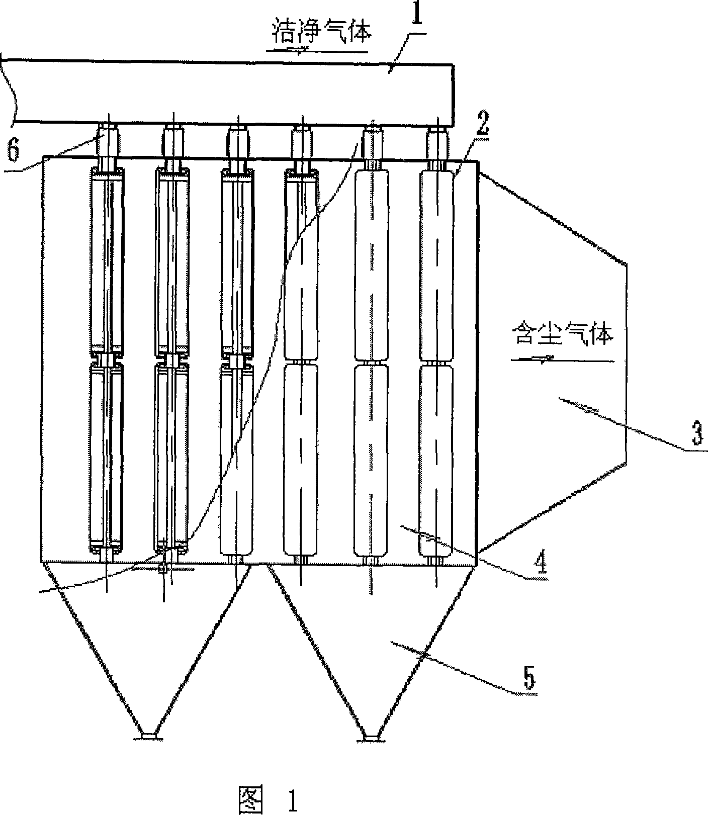
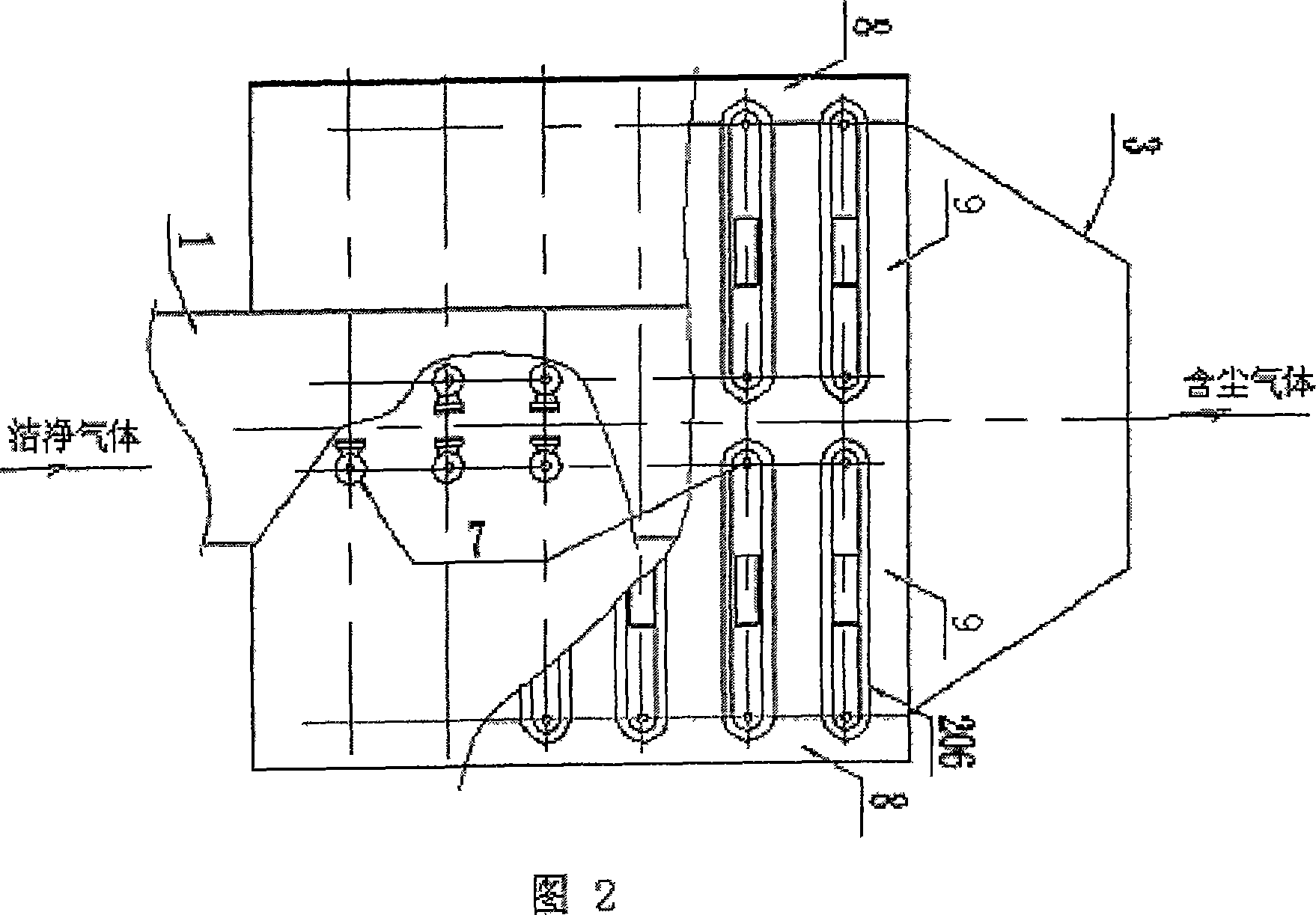
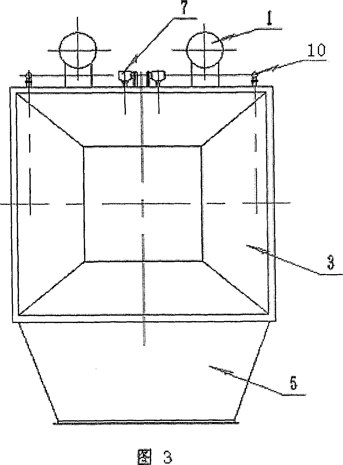
[0023] As shown in Figures 1 to 6, the dust remover of the present invention includes a dust removal chamber 4, an exhaust pipe 1 arranged on the dust removal chamber 4, an air inlet 3, and an ash hopper 5. The filter screen unit 2; As shown in Figure 4, the filter screen unit 2 includes the filter screen driving device 7 arranged on the dust removal chamber 4, the filter screen driving device 7 is arranged on the dust removal chamber 4 by the drive shaft 201 installed on the dust removal chamber 4 The driving wheel 208 on the chamber 4 and the driven wheel 205 arranged on the main pipe 203 of the cleaning gun consist of a drive shaft 201 passing through the dust removal chamber 4 and going out from the top of the dust removal chamber 4 to connect the driving power device. The upper and lower sides of the upper and lower sides, that is, the driving shaft 201 and the ash cleaning gun supervisor 203 outside the driving wheel 208 and the driven wheel 205 are provided with a sealin...


PUM


Abstract

The invention discloses a dust catcher, which comprises a dust cell, an exhaust column arranged on the dust cell, an air inlet and an ash hopper. At least a filtering screen unit is arranged in the dust cell, which comprises a filtering screen drive device, a sealing component is arranged at the two sides on and down the filtering screen drive device, the filtering screen covers on the drive device and the sealing component and forms a sealing filtering screen unit inner cavity, a soot cleaning device is arranged at a soot cleaning zone close to the filtering screen at one side of the filtering screen unit inner cavity, at least a connection opening which makes the filtering screen unit inner cavity connected with the exhaust column is arranged on the sealing component. The invention can realize continuous exhausting, dedusting and soot cleaning, and overcomes the defects that the existing dust catcher only can dedust fixedly, work and dedust intermittentedly brings increased dedusting load and lower dedusting capability, which has the advantages of high dedusting efficiency, less equipment investment, low running cost and convenient maintenance.

Description

technical field [0001] The invention belongs to dust removal equipment, and in particular relates to a dust remover using filter cloth for dust removal. Background technique [0002] The biggest advantage of the bag filter is its high dust removal efficiency. In the 1950s and 1960s, the bag filter was the main equipment for industrial dust removal in my country. In the 1970s and 1980s, people introduced the electrostatic precipitator, and the bag filter was once replaced by the electrostatic precipitator. In recent years, due to the continuous improvement of exhaust gas emission standards, bag filter has been favored by people again, and it is used in more and more occasions. Due to the unique structure of the bag filter, there are insurmountable defects in the bag filter. The disadvantages of the bag filter are as follows. 1. The damaged filter bag cannot be inspected, resulting in the need to replace the filter bag as a whole on a regular basis. The bag filter is compos...

Claims


Application Information

Patent Timeline
Patent Type & Authority Applications(China)
IPC IPC(8): B01D46/22
Inventor 刘克俭叶恒棣戴传德
Owner ZHONGYE-CHANGTIAN INT ENG CO LTD
Why Eureka
Try Eureka