Gear shift mechanism of engine speed changer

A shift mechanism and transmission technology, applied in the field of motor vehicle shift devices, can solve problems such as shift failure, burden, user trouble, etc., and achieve the effect of ensuring reliability and prolonging return time

Inactive Publication Date: 2008-01-23
LONCIN MOTOR
View PDF0 Cites 8 Cited by
  • Summary
  • Abstract
  • Description
  • Claims
  • Application Information

AI Technical Summary

Problems solved by technology

But, because the both sides of the dovetail portion of the driven sector gear of the shifting mechanism of existing engine transmission intersect with the tooth profile involutes of the teeth at the first and last ends of the gear portion respectively at the dedendum circle of the gear (see Fig. 1 and Figure 2), because the two sides of the dovetail of the driven sector gear intersect with the tooth profile involutes of the teeth at both ends of the gear at the root circle of the gear, the driving sector gear meshing with it has an excessively large rotation angle At this time, the side teeth of the driving sector gear have no limit interference after turning over the side teeth of the driven sector gear, so it is easy for the driving sector gear to continue to rotate after the side teeth pass over the side teeth of the driven sector gear, resulting The meshing of the driven sector gear is disengaged, which causes a serious problem of shift failure
Once the meshing of the driving and driven sector gears is disengaged, the gear shifting mechanism of the transmission cannot complete the gear shifting, and the transmission can only be repaired after breaking the case, causing great trouble and burden to the user

Method used


Image

  • Gear shift mechanism of engine speed changer
  • Gear shift mechanism of engine speed changer

Examples


Embodiment Construction

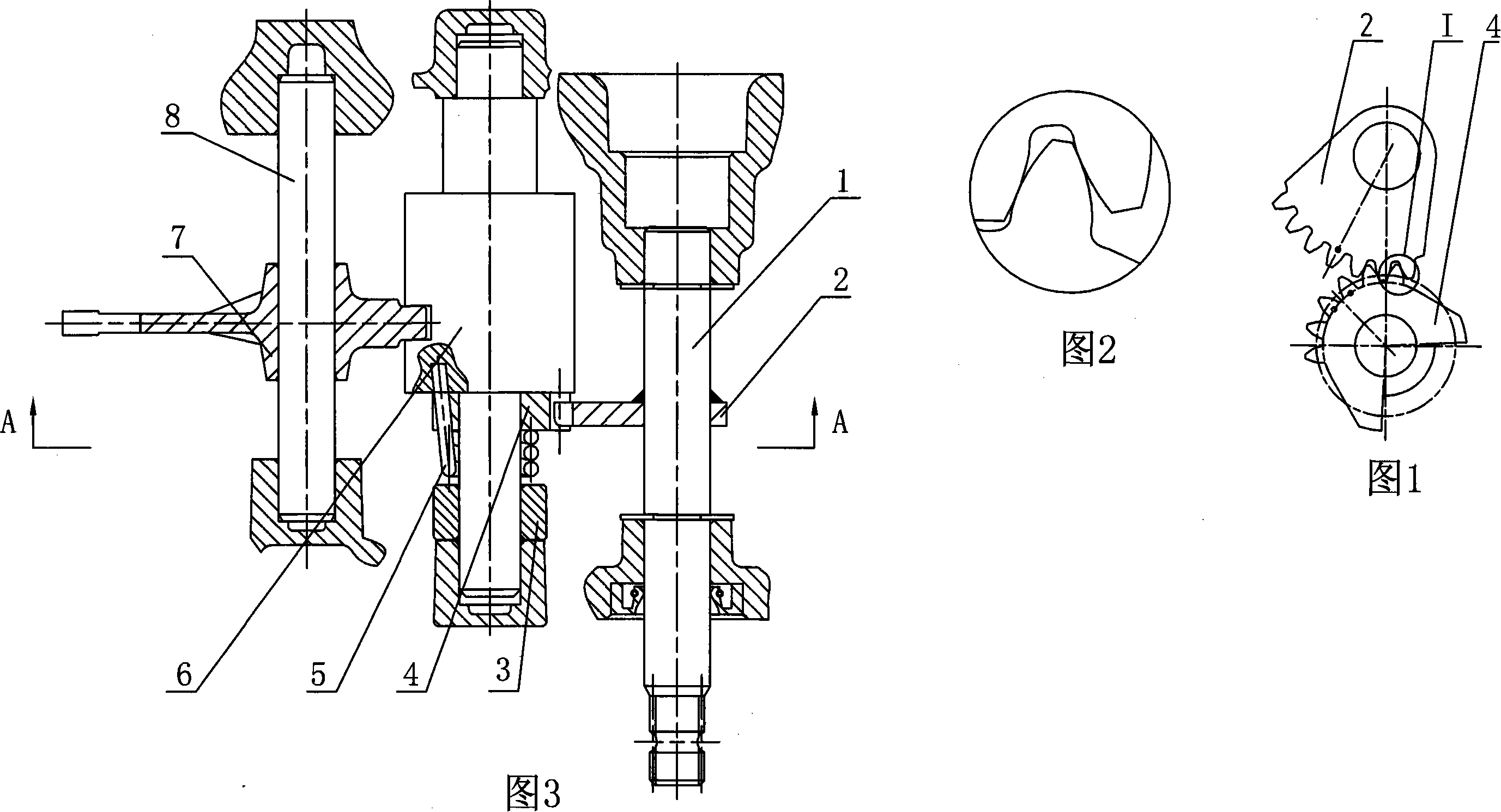
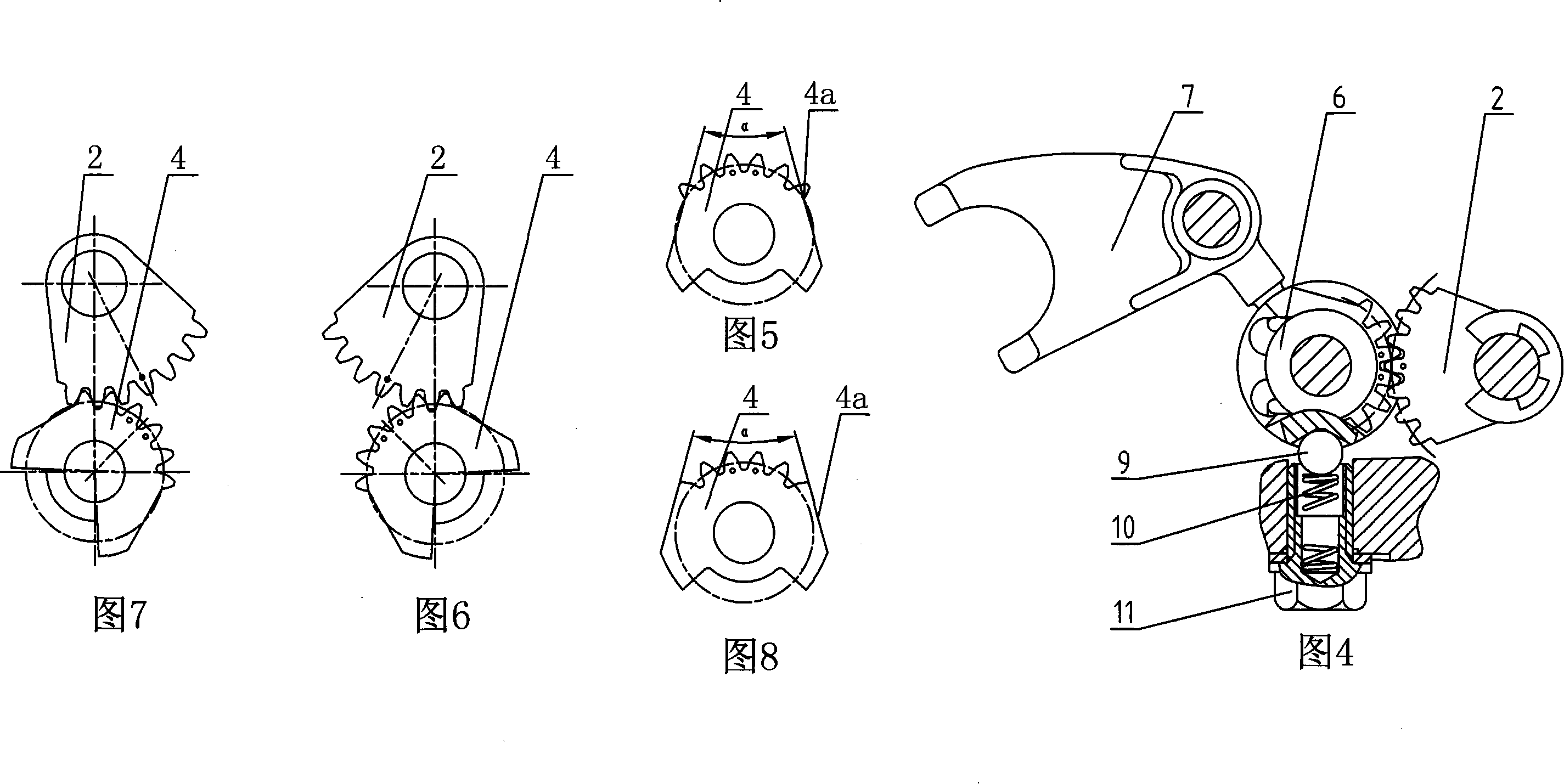
[0019] 3 to 5, the shift mechanism of the engine transmission of the present invention includes a shift shaft, a driving sector gear, a transmission hub, a driven sector gear, a fork shaft, and a shift fork. One end of the gearshift shaft 1 is installed in the crankcase, and the other end is used to connect with the gearshift pedal. The driving sector gear 2 is fixed on the shift shaft, and the driving sector gear 2 is welded and fixed on the shift shaft. The driven sector gear is fit on the shaft of the transmission hub with clearance, and forms a flexible connection with the transmission hub through the torsion spring. One end is connected, and the other end of the torsion spring 5 is inserted into the hole provided on the end face of the transmission hub 6 . The torsion spring 5 is in contact with the bushing 3 mounted on the transmission hub shaft, and the bushing 3 is in interference fit with the transmission hub 6, and the bushing is used to ensure the axial position of...


PUM


Abstract

The invention discloses a gearshift for a gearbox of an engine. Wherein, a driving segment gear is fixed on a gear-shifting shaft, a driven segment gear is clearance fit on the shaft of a shifting hub, and forms flexible connection with the shifting hub through a torsional spring; the driven segment gear is engaged with the driving segment gear; a drive fork is clearance fit on a drive-fork shaft; one end of the drive fork is clearance fit on a cam slot provided on the shifting hub; the driven segment gear is in dovetail segment gear structure, the two sides of the dovetail are correspondingly intercrossed with the tooth profile evolvent of the side teeth at the head and tail of the gear at any location between the indexing circle and the tooth crest circle of the gear; the extended lines of the two sides of the dovetail extend toward the gear and intercrosses. By a driven segment gear to avoid over rotation of the driving segment gear, the invention can avoid the disengagement between the driving and driven segment gear, and guarantee the reliability in gear shifting.

Description

technical field [0001] The invention relates to a gear shifting device of a motor vehicle, in particular to a gear shifting mechanism of a motorcycle engine transmission. Background technique [0002] At present, the shift mechanism of common motorcycle engine transmission is made up of shift shaft, driving sector gear, driven sector gear, transmission hub, shift fork shaft, shift fork etc. The driving sector gear is fixedly connected to the shift shaft, and the driven sector gear is fitted with clearance on the shaft of the transmission hub, forming a flexible connection with the transmission hub through a torsion spring. The driven sector gear is a dovetail sector gear, which meshes with the driving sector gear , one end of the shift fork with clearance fit on the shift fork shaft is inserted into the cam groove on the transmission hub, and the other end of the shift fork is used to move the gear on the transmission for axial displacement movement. When the external force ...

Claims


Application Information

Patent Timeline
Patent Type & Authority Applications(China)
IPC IPC(8): F16H59/02
Inventor 欧阳先军
Owner LONCIN MOTOR
Why Eureka
Try Eureka