Open-drain and open-source circuit output signal pin control device and method

An output signal, pin control technology, applied in the field of digital electronics, can solve the problems of large internal current, large static power consumption, etc., to achieve the effect of small internal current, low static power consumption, and extended service life

Inactive Publication Date: 2008-01-23
VIMICRO CORP
View PDF0 Cites 5 Cited by
  • Summary
  • Abstract
  • Description
  • Claims
  • Application Information

AI Technical Summary

Problems solved by technology

[0013] The embodiment of the present invention provides an output signal pin control device and method of an open-drain / open-source circuit to solve the problem that there may be a large internal current in the idle state of the open-drain / open-source circuit, resulting in a large static power consumption.

Method used


Image

  • Open-drain and open-source circuit output signal pin control device and method
  • Open-drain and open-source circuit output signal pin control device and method
  • Open-drain and open-source circuit output signal pin control device and method

Examples


Embodiment 1

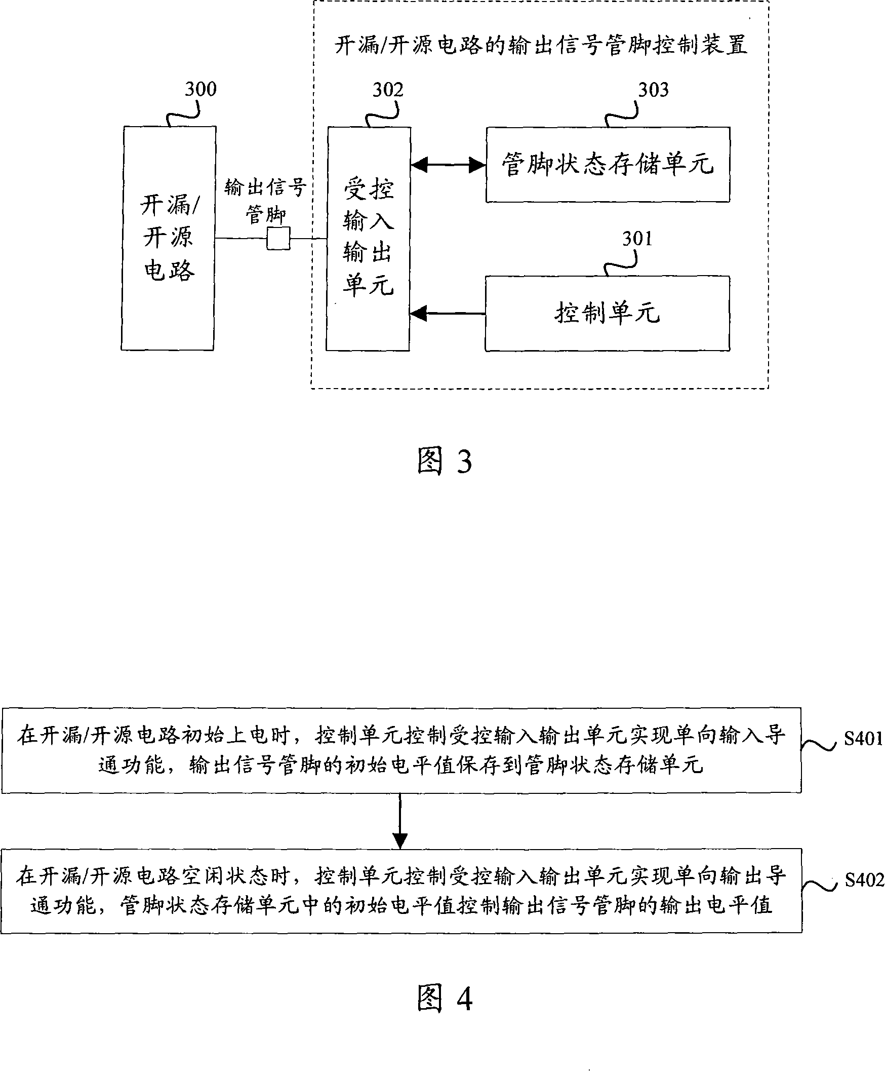
[0062] As shown in Figure 7, it is a specific embodiment of the present invention. This figure is a schematic diagram of the circuit structure of the open-drain circuit system, including the open-drain circuit and the output signal pin control device of the open-drain circuit. The open-drain circuit system is controlled by the system internal The function can realize the conversion from the initial state to the normal working state, and the mutual conversion between the normal working state and the idle state.

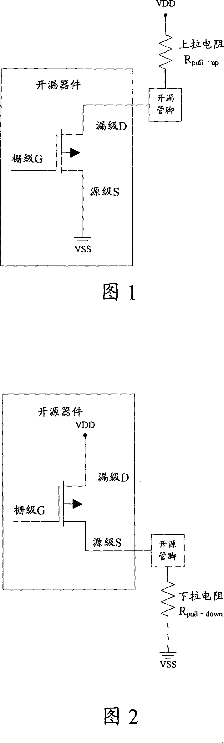
[0063] The open-drain device 700 in the figure, that is, the MOS FET and the pull-up resistor R pull-up To form a complete open-drain circuit, when the open-drain circuit is in an idle state and the open-drain pin is low, there is a large internal current, resulting in a large static power consumption. Using the scheme provided by the embodiment of the present invention, an output signal pin control device of the open-drain circuit is added to the open-drain circuit, w...

Embodiment 2

[0073] As shown in Figure 8, it is a specific embodiment of the present invention. This figure is a schematic diagram of the circuit structure of the open source circuit system, including the open source circuit and the output signal pin control device of the open source circuit. The open source circuit system can realize the initial control function through the internal control function of the system. State transition to normal working state, and mutual transition between normal working state and idle state.

[0074] The open source device 800 in the figure, that is, the MOS FET and the pull-down resistor R pull-down To form a complete open source circuit, when the open source circuit is in an idle state and the open source pin is at a high level, there is a large internal current, resulting in a large static power consumption. Using the solution provided by the embodiment of the present invention, the output signal pin control device of the open source circuit is added to th...


PUM


Abstract

The present invention discloses an output signal pin control device and a method for an open leakage/open source circuit to eliminate high static power consumption of an open leakage/open source circuit at an idle state. The control device comprises a control unit, a controlled input and output unit and a pin state memory unit. Wherein, the control unit controls a unidirectional input switch-on of the controlled input and output unit during initial power supply to the open leakage/open source circuit. An initial level value output by an output signal pin is transmitted to the pin state memory state for storage through the controlled input and output unit. During idle state of the open leakage/open source circuit, the control unit controls the controlled input and output unit to output a unidirectional output. The initial level value in the pin state memory unit is output to the output signal pin through the controlled input and output unit. In addition, the present invention also provides an open leakage/open source circuit system.

Description

technical field [0001] The invention relates to digital electronic technology, in particular to an output signal pin control device and method of an open-drain / open-source circuit. Background technique [0002] An open drain (Open Drain) circuit refers to a circuit with a drain (Drain) of a Metal Oxide Semiconductor Field Effect Transistor (MOS FET) as an output terminal. The general structure of an open-drain circuit is to add a pull-up resistor to the circuit outside the drain. The complete open-drain circuit consists of an open-drain device and a pull-up resistor. An open-drain device refers to a circuit that includes a MOS FET and uses the drain of the MOS FET as the output terminal. device. As shown in Figure 1, it is a schematic diagram of the structure of an open-drain circuit composed of MOS FETs. The drain of the open-drain device MOS FET is an output signal pin, referred to as an open-drain pin, R pull-up It is a pull-up resistor; VDD is the power supply, and VSS...

Claims


Application Information

Patent Timeline
Patent Type & Authority Applications(China)
IPC IPC(8): H03K17/687
Inventor 王振国
Owner VIMICRO CORP
Why Eureka
Try Eureka