Method for obtaining locating information of user's set
A technology of user equipment and location information, applied in the direction of selection devices, radio transmission systems, electrical components, etc., can solve the problems of wasting network resources, complicated acquisition process, and inability to obtain location, etc., achieve short execution time, simple process, and save network resource effect
- Summary
- Abstract
- Description
- Claims
- Application Information
AI Technical Summary
Problems solved by technology
Method used
Image
Examples
Embodiment 1
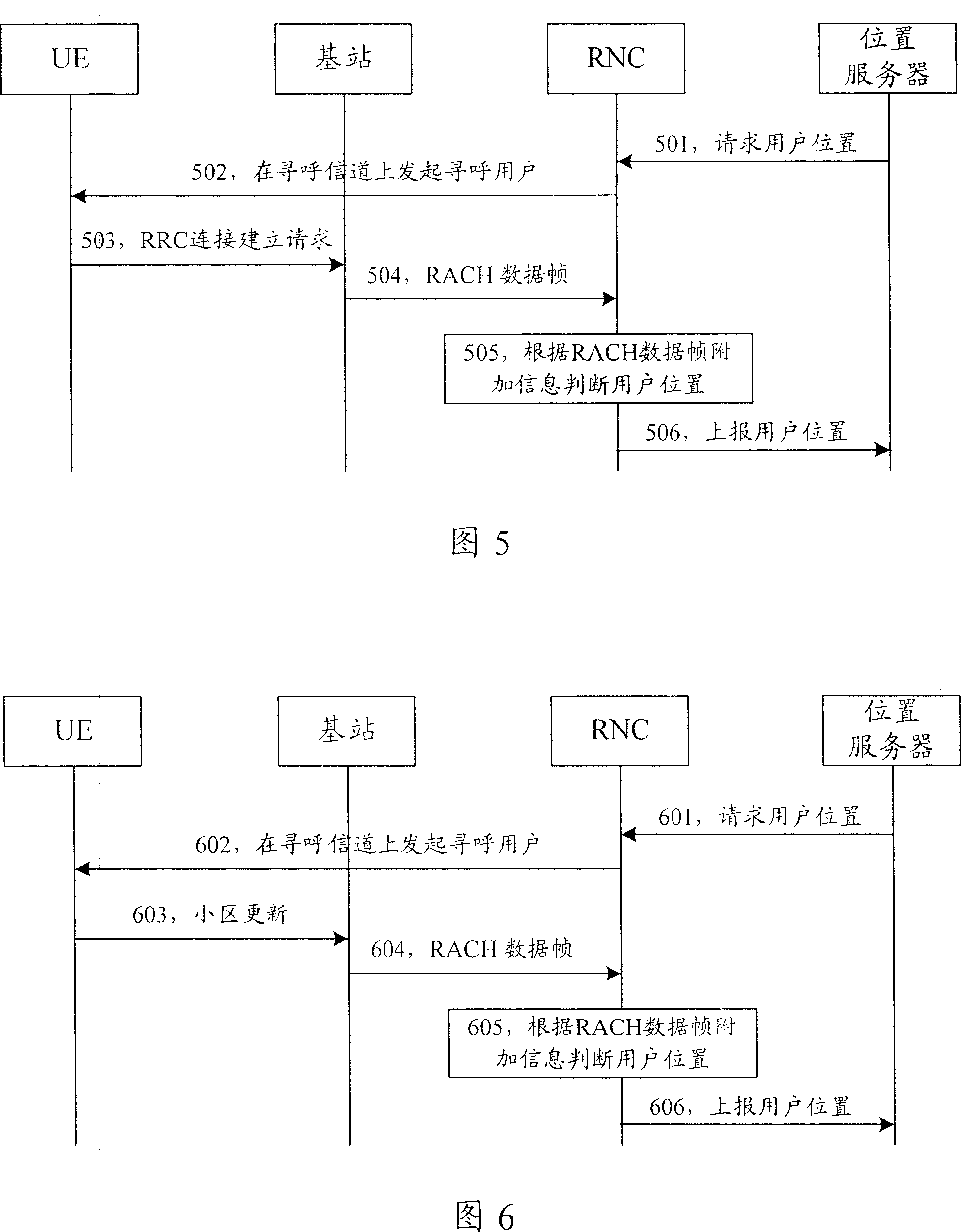
[0057] FIG. 5 is a flowchart of a method for acquiring location information of a user equipment in Embodiment 1 of the present invention. As shown in Figure 5, taking the UE in an idle state as an example, the method for obtaining the location information of the user equipment in the present invention includes the following steps:
[0058] Step 501, when the location server needs to obtain the location of the UE, it sends a request to the RNC.
[0059] In step 502, the decision system of the RNC determines that there is no RRC connection between the UE and the base station, and initiates the paging of the UE by the base station, and the base station pages the UE through a paging channel.
[0060] Step 503, the paged UE is in an idle state, and sends an RRC connection establishment request message to the base station through RACH after receiving the paging.
[0061] Step 504, after the base station receives the RRC connection establishment request from the UE through the RACH,...
Embodiment 2
[0066] FIG. 6 is a flowchart of a method for acquiring location information of a user equipment in Embodiment 2 of the present invention. As shown in Figure 6, taking the UE in the CELL_PCH state or URA_PCH state as an example, the method for obtaining the location information of the user equipment in the present invention includes the following steps:
[0067] Steps 601 to 602, when the location server needs to obtain the location of the UE, it sends a request to the RNC, and the judgment system of the RNC judges that there is no RRC connection between the UE and the base station, and then initiates the paging of the UE by the base station, and the base station passes The paging channel pages the UE.
[0068] The above two steps are the same as the operation process of step 501 to step 502 in the first embodiment.
[0069] In step 603, the UE is in the CEL_LPCH state or the URA_PCH state, and after receiving the paging, sends cell update (Cell Update) information to the base...
Embodiment 3
[0076] FIG. 7 is a flowchart of a method for acquiring location information of a user equipment in Embodiment 3 of the present invention. As shown in Figure 7, taking the UE in the CELL_FACH state as an example, the method for obtaining the location information of the user equipment in the present invention includes the following steps:
[0077] Step 701, when the location server needs to obtain the location of the UE, it sends a request to the RNC.
[0078] In step 702, the RNC sends a UE capability request message to the UE, requesting to obtain UE capability information.
[0079] In this step, the RNC requests to obtain the capability information of the UE, and may also request to obtain other information from the UE.
[0080] In step 703, the UE is in the CELL_FACH state, and after receiving the request, sends its capability information to the base station through RACH.
[0081] Step 704: After receiving the capability information from the UE via RACH, the base station m...
PUM
 Abstract
Description
Claims
Application Information
 - R&D
- Intellectual Property
- Life Sciences
- Materials
- Tech Scout
- Unparalleled Data Quality
- Higher Quality Content
- 60% Fewer Hallucinations
Browse by: Latest US Patents, China's latest patents, Technical Efficacy Thesaurus, Application Domain, Technology Topic, Popular Technical Reports.
© 2025 PatSnap. All rights reserved.Legal|Privacy policy|Modern Slavery Act Transparency Statement|Sitemap|About US| Contact US: help@patsnap.com


