System fault detecting method and device

A technology for automatic detection of system faults, applied in the field of communication, can solve problems such as inconvenience, inability to accurately determine complex fault types and causes, and large intervention workload, so as to reduce manual intervention and reduce average fault maintenance time, the effect of improving reliability and maintainability

Inactive Publication Date: 2008-01-23
于京杰
View PDF0 Cites 17 Cited by
  • Summary
  • Abstract
  • Description
  • Claims
  • Application Information

AI Technical Summary

Problems solved by technology

These methods are based on the external performance of each functional unit of the site to realize the identification and division of the normal function of the system unit. They cannot accurately determine the type and cause of complex faults, and require a large amount of work for later intervention by the user. It will cause inconvenience in actual use, and the improvements needed include:

Method used


Image

  • System fault detecting method and device
  • System fault detecting method and device
  • System fault detecting method and device

Examples


Embodiment Construction

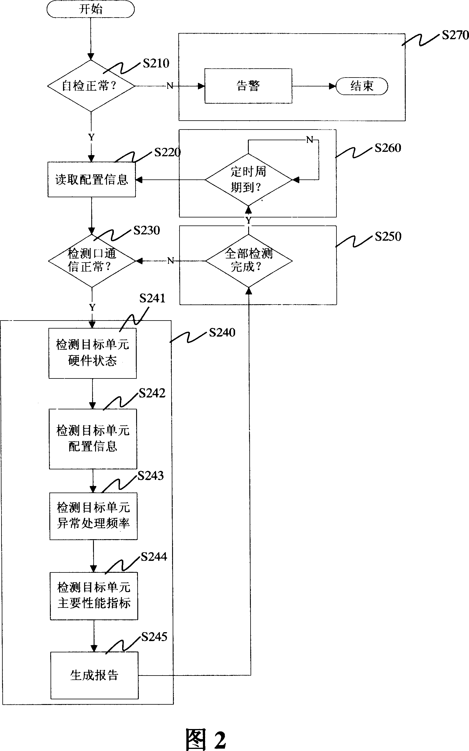
[0045] The following describes the implementation of the technical solution in further detail in conjunction with the accompanying drawings, basically in the order of the accompanying drawings:

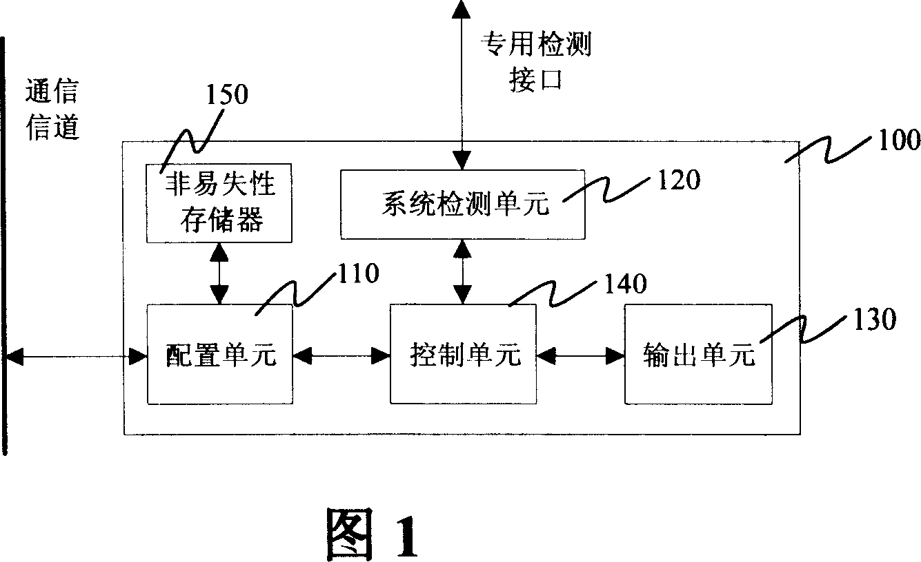
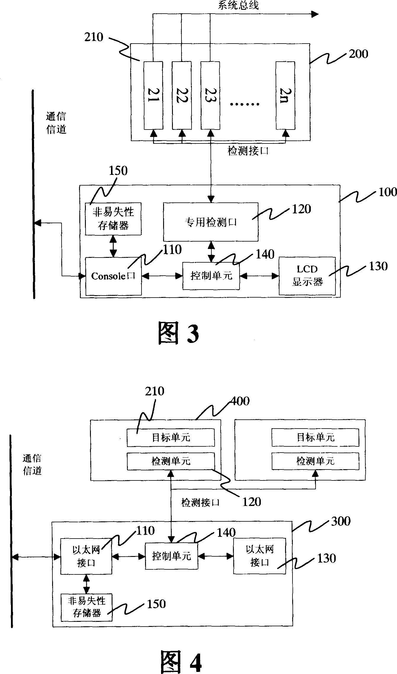
[0046] The system fault detection device 100 of the present invention is mainly composed of 4 functional units, including a configuration unit 110, a detection unit 120, an output unit 130, and a control unit 140.

[0047] Figure 1 is a schematic diagram of a system fault detection device. As shown in FIG. 1, the detection device 100 can be divided into 4 functional units, and the functional units are connected together by an internal bus to form a complete system. The configuration unit 110 receives user configuration information from the man-machine interface and saves it in the non-volatile memory 150 inside the detection device. The non-volatile memory 150 may be an EEPROM (Electrically Erasable Programmable Read-Only Memory). The configuration information can reach the control unit 1...


PUM


Abstract

The present invention provides an automatic system failure detecting device, which is connected with a monitored system to automatically detect operating state of the monitored system, including equipments and units of optical communication and transmission node system, to report to senior administrators or warn and comprises a configuration unit to receive user configuration information from a communication channel and transmit the information to a control unit, a control unit connected with the configuration unit to dispatch the configuration information to a detecting unit and receive detecting results fed back by the detecting unit, a detecting unit connected with the control unit and a monitored system through a detecting interface to detect hardware state, configuration information, function index and/or performance index of the monitored system, generate the detecting result, feed the detecting result to the control unit, and an output unit communicated with the control unit to output the detecting result sent by the control unit. In addition, the present invention also provides a method to automatically detect system failures with the device above.

Description

Technical field [0001] The invention relates to a method and device for automatic detection and fault discovery of control, transmission site and sub-system functional units in the communication field, especially in the field of optical communication for the state detection method and device of transmission node system equipment and units. Background technique [0002] With the continuous advancement and development of technology in the field of modern communications, ultra-long-distance, ultra-large-capacity transmission systems have become more and more widely used. Because long-distance backbone transmission often needs to pass through sparsely populated areas, its relay sites are often unmanned or few people on duty. When the system equipment fails, the corresponding management personnel will carry out manual fault location and troubleshooting, and the work efficiency is relatively low. [0003] With the continuous expansion of the communication system business field, the req...

Claims


Application Information

Patent Timeline
Patent Type & Authority Applications(China)
IPC IPC(8): H04B10/08H04B10/07H04L12/24
Inventor 邹红兵
Owner 于京杰
Why Eureka
Try Eureka